9300 servo plc, System blocks – Lenze DDS Target 9300 Servo PLC V8.x User Manual
Page 50
2.9
DFOUT_IO_DigitalFrequency (node number 22)
9300 Servo PLC
System blocks
2−44
L
9300 Servo PLC EN 5.1
Configuration of the digital frequency output signal
·
The type of the digital frequency output signal is configured under C0540:
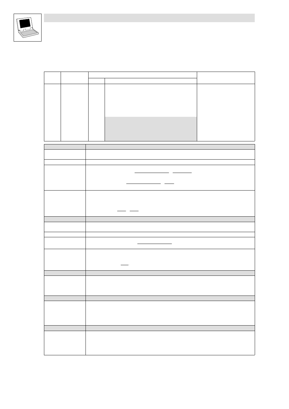
Code
LCD
Possible settings
Info
Lenze
Selection
C0540 Function
2
Digital frequency output: Function
·
X9 is inhibited if 0, 1, or 2 have
been selected.
·
DFOUT_nIn_v = 0 if 4 or 5 have
been selected.
·
The input signals are buffered
electrically.
0
DFOUT_nOut_v as %
1
DFOUT_nOut_v as rpm
2
Incremental encoder simulation + zero pulse
4
X9 is output on X10
5
X8 is output on X10
C0540 = 0
Output of an analog signal
Function
The input signal DFOUT_nOut_v is interpreted as an analog signal [%] and is output as a frequency signal on the
digital frequency output X10.
Scaling
100 %
º (INT)16384 º C0011 (n
max)
Transmission function
f [Hz]
+ DFOUT_nOut_v [%] @ Increments from C0030
100
@
C0011 (n
max
)
60
DFOUT_nIn_v
+ f [Hz] @
60
Increments from C0030
@ 2
14
15000
Example
·
DFOUT_nOut_v = 50 %
·
C0030 = 3, this corresponds to a number of increments of 2048 increments/revolution
·
C0011 = 3000 rpm
f [Hz]
+ 50 % @ 2048
100
@ 3000
60
+ 51200 Hz
C0540 = 1
Output of a speed signal
Function
The input signal DFOUT_nOut_v is interpreted as a speed signal [rpm] and is output as a frequency signal on the
digital frequency output X10.
Scaling
15000 rpm
º (INT)16384
Transmission function
f [Hz]
+ DFOUT_nOut_v [rpm] @
Increments from C0030
60
Example
·
DFOUT_nOut_v = 3000 rpm
·
C0030 = 3, this corresponds to a number of increments of 2048 increments/revolution
f [Hz]
+ 3000 rpm @ 2048
60
+ 102400 Hz
C0540 = 2
Encoder simulation of the resolver with zero track in resolver position
Function
·
The function is used if a resolver is connected to X7.
·
The encoder constant for the output X10 is set under C0030.
·
The output of the zero pulse referring to the rotor depends on how the resolver is attached to the motor.
·
The zero pulse can be shifted by +360 ° under C0545 (65536 inc = 360 °).
C0540 = 4
Direct output of X9
Function
Use of X9 as a digital frequency input.
·
The input signal at X9 is electrically amplified and is directly output to X10.
·
The signals depend on the assignment of input X9.
·
C0030 and C0545 have no function.
·
The zero track is only output if it is also connected to X9.
C0540 = 5
Direct output of X8
Function
Use of X8 as an input for incremental encoders or sin/cos encoders.
·
The input signal at X8 is electrically amplified and is directly output to X10.
·
The signals depend on the assignment of input X8.
·
C0030 and C0545 have no function.
·
The zero track is only output if it is also connected to X8.