Definition of inputs/outputs, 9300 servo plc, Preface and general information – Lenze DDS Target 9300 Servo PLC V8.x User Manual
Page 12: 5 definition of inputs/outputs
9300 Servo PLC
Preface and general information
1−6
l
9300 Servo PLC EN 5.1
1.2.5
Definition of inputs/outputs
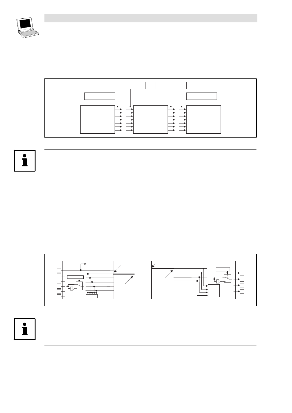
The application program is connected with the hardware by linking system blocks with program
organisation units (POUs):
SB
SB-Output
SB-Input
SB
POU-Input
POU-Output
POU
Fig. 1−1
Principle: Linking of system blocks with a program organisation unit (POU)
Tip!
Inputs and outputs are always classified from the program’s point of view.
·
Logic SB inputs are hardware outputs of the PLC.
·
Logic SB outputs are hardware inputs of the PLC.
Example: System block DIGITAL_IO of the 9300 Servo PLC
If you want to use the digital input 1 and the digital output 1 of the 9300 Servo PLC, proceed as
follows:
1. Link the SB DIGITAL_IO explicitly with the DDS control configuration.
(
2. Access to digital input 1:
Assign the system variable DIGIN_bIn1_b to a POU input.
3. Access to digital output 1:
Assign the system variable DIGOUT_bOut1_b to a POU output.
E1
E2
E3
E4
E5
1
0
C0114/1...5
DIGIN
DIGIN_bIn1_b
DIGIN_bIn2_b
DIGIN_bIn3_b
DIGIN_bIn4_b
DIGIN_bIn5_b
C0443
28
DCTRL -X5/28
X5
DIGIN_bCInh_b
1
A1
A2
A3
A4
1
0
C0118/1...4
DIGOUT
C0444/4
C0444/3
C0444/2
C0444/1
X5
1
DIGOUT_bOut1_b
DIGOUT_bOut2_b
DIGOUT_bOut3_b
DIGOUT_bOut4_b
SB-OUT
SB-IN
POU
POU-IN
POU-OUT
Fig. 1−2
Principle: Linking of the 9300 Servo PLC system block DIGITAL_IO with a POU
Tip!
According to the IEC61131−3 standard, only one copy of the digital input 1 and the digital output 1
may be transferred.