Dfout_io_digitalfrequency (node number 22), Inputs_dfout / outputs_dfout, 9300 servo plc – Lenze DDS Target 9300 Servo PLC V8.x User Manual
Page 49: 9 dfout_io_digitalfrequency (node number 22), System blocks, 1 inputs_dfout / outputs_dfout
9300 Servo PLC
System blocks
2.9
DFOUT_IO_DigitalFrequency (node number 22)
2−43
L
9300 Servo PLC EN 5.1
2.9
DFOUT_IO_DigitalFrequency (node number 22)
2.9.1
Inputs_DFOUT / Outputs_DFOUT
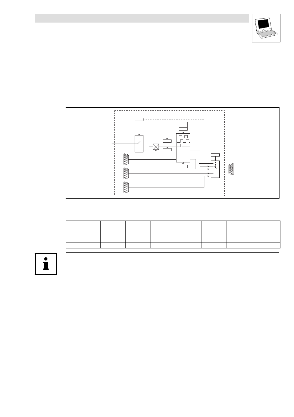
This SB converts internal speed signals into frequency signals and outputs them to X10.
·
The transmission is very precise with the remainder being considered (no offset and gain
errors).
DFOUT_IO_DigitalFrequency
X10
C0540
0
1
2
4
5
0
1
2
4
5
CTRL
C0545
C0540
C1799
C0030
C0547
n
ma x
C0540
X8
X9
DFOUT_nOut_v
DFOUT_nIn_v
X7
C0549
Fig. 2−19
Digital frequency output (DF_OUT)
System variables
Variable
Data type
Signal type
Address
Display
Code
Display
Format
Note
DFOUT_nOut_v
Integer
Velocity
%QW22.0
C0547
C0549
dec [%]
dec [rpm]
DFOUT_nIn_v
Integer
Velocity
%IW22.0
−
−
Tip!
The process image is newly created for every task the SB is used in.
·
If DFOUT_nIn_v and DFOUT_nOut_v are used in several tasks, an own process image of the
SB is created for each of these tasks.
·
This process is different from the previous process image creation principle!
·
The signals of the digital frequency output X10 are TTL−compatible.
·
The output signal corresponds to the simulation of an incremental encoder:
– Track A, track B and the zero track (if necessary) as well as the corresponding inverted
tracks are output with tracks shifted by 90°.