9300 servo plc, Appendix, 6 code table – Lenze DDS Target 9300 Servo PLC V8.x User Manual
Page 139
9300 Servo PLC
Appendix
3.6
Code table
3−133
L
9300 Servo PLC EN 5.1
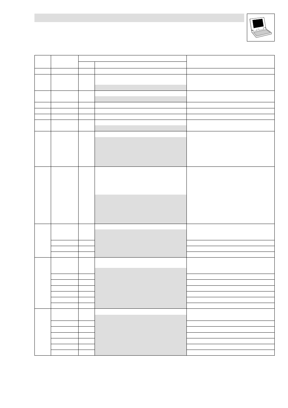
Code
Information
Possible settings
LCD
Code
Information
Selection
Lenze
LCD
C0209 DL info 3
g
Download info 3
C0250 FCODE 1Bit
0
Freely configurable code (digital signals)
·
FCODE_bC250_b
0
1
C0254 Vp angle CTRL
0.4000
Gain of angle controller (V
p
)
0.0000
{0.0001}
3.9999
C0300
Internal error diagnostics
C0301
Internal error diagnostics
C0302
Internal error diagnostics
C0350 CAN address
1
System bus: Node address
1
{1}
63
C0351 CAN baud rate
0
System bus: Baud rate
0
500 kbps
1
250 kbps
2
125 kbps
3
50 kbps
4
1000 kbps
5
20 kbps
C0352 CAN mst
0
System bus: Master/slave configuration of the PLC
·
With selection 1 or 2, the PLC sends a system bus
boot−up and is thus quasi" master.
·
Additional information about the "heartbeat" and "node
guarding" function can be found in the Manual for the
function library LenzeCanDSxDrv.lib.
0
Slave (boot−up not active)
1
Master (boot−up active)
2
Master with Node Guarding
(SyncReceived no longer possible)
3
Slave and "heartbeat" producer
4
Slave with node guarding
C0353 CAN addr sel
System bus: Source for PDO identifiers
0
Identifier assignment under C0350 + basic identifier
1
Identifier assignment under C0354/x
1
0
CAN1_IN/OUT
2
0
CAN2_IN/OUT
3
0
CAN3_IN/OUT
C0354 CAN addr
System bus: Definition of individual PDO identifiers
·
Value to be entered = Identifier − 384
1
{1}
512
1
129
CAN1_IN
2
1
CAN1_OUT
3
257
CAN2_IN
4
258
CAN2_OUT
5
385
CAN3_IN
6
386
CAN3_OUT
C0355 CAN Id
g
System bus: PDO identifiers
385
{1}
896
1
CAN1_IN
2
CAN1_OUT
3
CAN2_IN
4
CAN2_OUT
5
CAN3_IN
6
CAN3_OUT