Festo Контроллер позиционирования CPX-CMPX User Manual
Page 52
2. Assembly
2−8
Festo P.BE−CPX−SYS−EN en 0902e
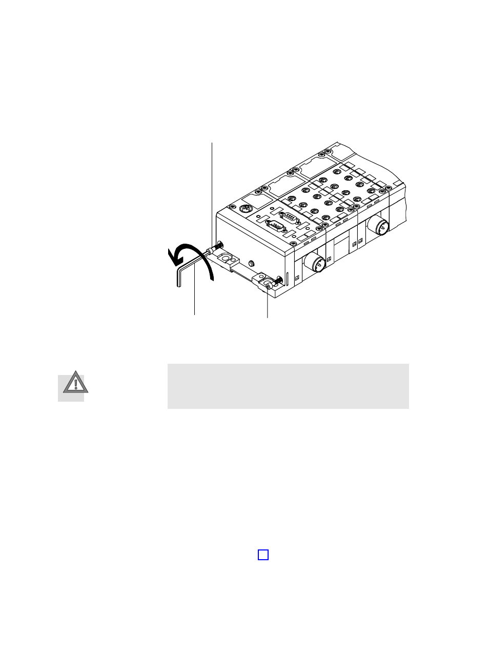
1
Tie rod screw
2
Allen key size 3
1
1
2
Fig. 2/2:
Dismantling electric I/O modules
Caution
Make sure that the electric plug connectors of the inter−
linking blocks are
not bent.
3. Loosen the electrical plug connectors on the relevant
interlinking block by taking the interlinking block apart
carefully and without tilting it.
4. Now push the modules to the left of the module to be
replaced approx. 3 cm to the left.
5. Now push the module to be replaced approx. 1.5 cm to
the left.
6. Make sure that the tie rod lies over the tie rod groove of
the module to be replaced by shifting the module accordĆ
ingly (see arrow A in Fig. 2/3).