Allied Telesis AT 8000/8POE User Manual
Page 135
AT-S81 Management Software User’s Guide
Section I: Using the Menus Interface
135
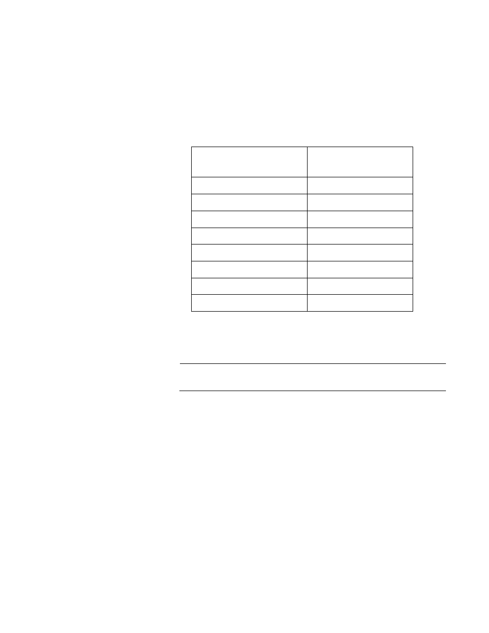
Each port on the switch has four priority queues, 0 (low) to 3 (high). When
a tagged packet enters a switch port, the switch responds by placing the
packet into one of the queues according to the assignments shown in
Table 5. A packet in a high priority queue is typically transmitted out a port
sooner than a packet in a low priority queue.
For example, a tagged packet with a priority tag of 6 is placed in the
egress port’s highest priority queue of 3, while a packet with a priority tag
of 1 is placed in the lowest priority queue.
Note
QoS is disabled by default on the switch.
You can customize these priority-to-queue assignments using the AT-S81
management software. The procedure for changing the default mappings
is found in “Mapping CoS Priorities to Egress Queues” on page 137.
You can configure a port to completely ignore the priority levels in its
tagged packets and instead use a temporary priority level assigned to the
port. For instance, perhaps you decide that all tagged packets received on
port 4 should be assigned a priority level of 5, regardless of the priority
level in the packets themselves. The procedure for overriding priority
levels is explained in “Configuring CoS” on page 140.
CoS relates primarily to tagged packets rather than untagged packets
because untagged packets do not contain a priority level. By default, all
untagged packets are placed in a port’s Q0 egress queue, the queue with
the lowest priority. But you can override this and instruct a port’s untagged
frames to be stored in a higher priority queue. The procedure for this is
also explained in “Configuring CoS” on page 140.
Table 5. Default Mappings of IEEE 802.1p Priority Levels to Egress Port
Priority Queues
IEEE 802.1p Traffic Class
Egress Port Priority
Queue
0
0
1
0
2
0
3
1
4
2
5
2
6
3
7
3