Table 24. front panel to rack rail dimensions – Allied Telesis SwitchBlade x3106 User Manual
Page 87
SwitchBlade x3106 Installation Guide
87
Position F installs the chassis with the rear panel flush with the
front of the equipment rack.
To install the rack mount brackets in position “E,” you have to
remove the two chassis screws from the bottom-middle section of
the chassis and re-install them in front where the rack mount
bracket screws were originally, as shown in Figure 40 on page 88.
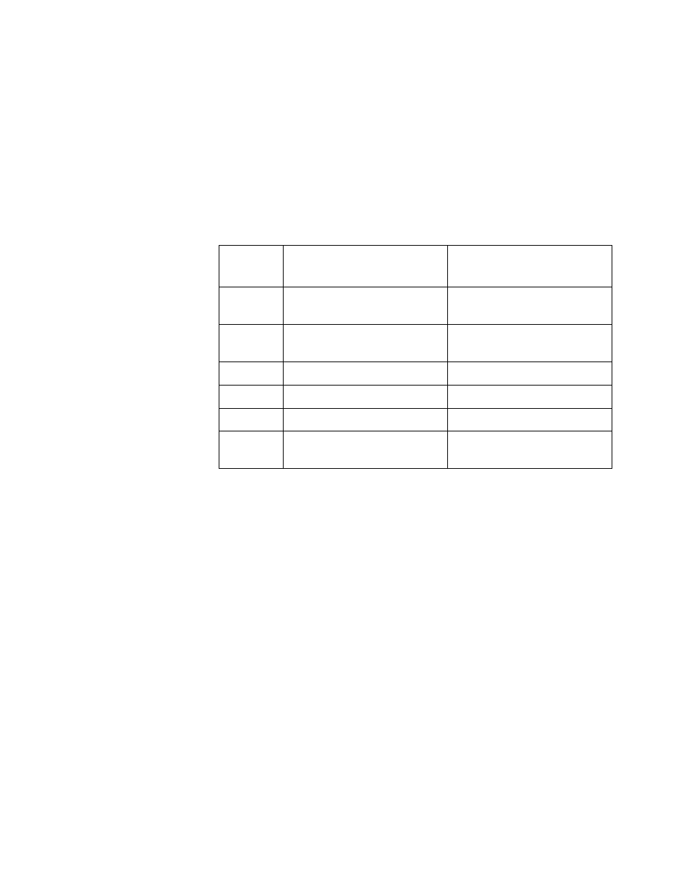
The dimension (X) between the front panel and the rack rails is
given for each rack mounting bracket position in Table 24.
Table 24. Front Panel to Rack Rail Dimensions
Figure #
Front Panel Position
Dimension X
Front Panel to Rack Rail
A
(Factory Installed - Flush)
3.69 mm (0.145 in)
B
(Recessed)
-27.39 mm (-1.078 in)
C
27.39 mm (1.078 in)
D
47.71 mm (1.878 in)
E
140.85 mm (5.545 in)
F
(Reverse Position)
374.16 mm (14.731 in)
- AT-GS908M (54 pages)
- AT-x230-10GP (80 pages)
- AT-GS950/48PS (64 pages)
- AT-GS950/10PS (386 pages)
- AT-GS950/16PS (386 pages)
- AT-GS950/48PS (386 pages)
- AT-9000 Series (258 pages)
- AT-9000 Series (1480 pages)
- IE200 Series (70 pages)
- AT-GS950/48 (378 pages)
- AT-GS950/48 (60 pages)
- AT-GS950/48 (410 pages)
- AT-GS950/8 (52 pages)
- SwitchBlade x8106 (322 pages)
- SwitchBlade x8112 (322 pages)
- SwitchBlade x8106 (240 pages)
- SwitchBlade x8112 (240 pages)
- AT-TQ Series (172 pages)
- AlliedWare Plus Operating System Version 5.4.4C (x310-26FT,x310-26FP,x310-50FT,x310-50FP) (2220 pages)
- FS970M Series (106 pages)
- 8100L Series (116 pages)
- 8100S Series (140 pages)
- x310 Series (116 pages)
- x310 Series (120 pages)
- AT-GS950/24 (404 pages)
- AT-GS950/24 (366 pages)
- AT-GS950/16 (44 pages)
- AT-GS950/16 (404 pages)
- AT-GS950/16 (364 pages)
- AT-GS950/8 (364 pages)
- AT-GS950/8 (52 pages)
- AT-GS950/8 (404 pages)
- AT-8100 Series (330 pages)
- AT-8100 Series (1962 pages)
- AT-FS970M Series (330 pages)
- AT-FS970M Series (1938 pages)
- SwitchBlade x3106 (288 pages)
- SwitchBlade x3112 (294 pages)
- SwitchBlade x3112 (222 pages)
- AT-S95 CLI (AT-8000GS Series) (397 pages)
- AT-S94 CLI (AT-8000S Series) (402 pages)
- AT-IMC1000T/SFP (23 pages)
- AT-IMC1000TP/SFP (24 pages)
- AT-SBx3106WMB (44 pages)