Allied Telesis SwitchBlade x3106 User Manual
Page 187
SwitchBlade x3106 Installation Guide
187
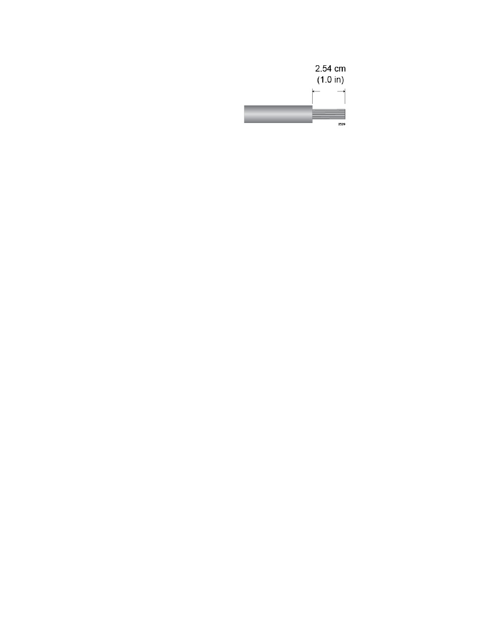
Figure 142. Stripping Solid or Stranded DC Power Wires
2. Verify that the On/Off switch on the AT-SBxPWRSYS1 DC Power
Supply is in the Off position. Refer to Figure 128 on page 175.
3. Use a #1 Phillips-head screwdriver to loosen the two screws on the
plastic cover over the positive and negative terminals on the power
supply and slide the cover to the right, as shown in Figure 129 on page
176. You may need to lift the locking handle slightly to access the
bottom screw.
4. Use a #3 Phillips-head screwdriver to remove the two screws from the
positive and negative terminals, as shown in Figure 130 on page 176.
5. Wrap the positive lead wire clockwise around one of the terminal
screws and secure the screw and wire to the positive terminal
connection on the terminal block with a #3 Phillips-head screwdriver.
The positive terminal is on the left. You may attach the wire to the
terminal so that it extends either above or below the terminal block.
Figure 143 on page 188 shows the wire above the terminal block.
Allied Telesis recommends tightening the screw to 30 to 40 inch-lbs.