Power supply slots – Allied Telesis SwitchBlade x3106 User Manual
Page 25
SwitchBlade x3106 Installation Guide
25
Figure 9. Slots for the Ethernet Line and Control Cards
Slots 0 to 3 are for Ethernet line cards. The cards may be installed in any
order or variety in the slots.
Slot 4 is for the AT-SBx31CFC Central Fabric Controller card. The chassis
must have at least one controller card.
Slot 5 may be used with either an Ethernet line card or a second controller
card. A second controller card adds management redundancy and
increases the available traffic bandwidth of the chassis.
Power Supply
Slots
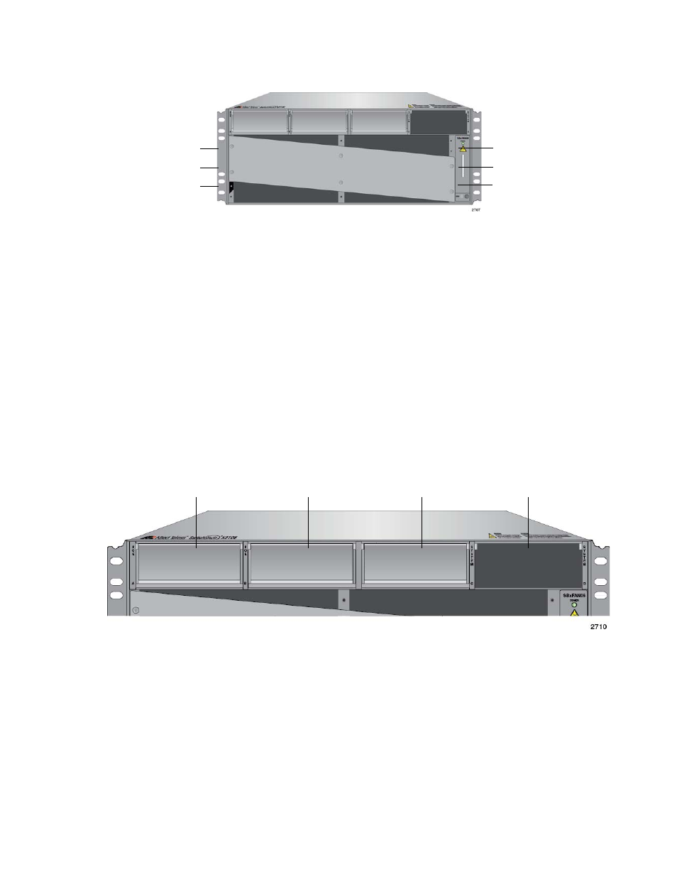
The chassis has four power supply slots, labelled A to D, across the top of
the front panel of the chassis, as shown in Figure 10.
Figure 10. Power Supply Slots
The two right hand slots are for the AT-SBxPWRSYS1 Power Supply,
which supplies power to the Ethernet line cards, controller cards, and fan
module. The only chassis component not powered by the module is the
PoE feature on the twisted pair ports on the AT-SBx31GP24 PoE Line
Card.
There are AC and DC versions of the AT-SBxPWRSYS1 Power Supply.
Refer to Figure 4 on page 21 for illustrations of the modules.
Slot 0 - Line Card
Slot 2 - Line Card
Slot 4 - Controller
Slot 1 - Line Card
Slot 3 - Line Card
Slot 5 - Line or
Controller Card
Card
Slot A
AT-SBxPWRPOE1
Power Supply
Slot B
AT-SBxPWRPOE1
Power Supply
Slot C
AT-SBxPWRSYS1
Power Supply
Slot D
AT-SBxPWRSYS1
Power Supply