Figure 144: connecting the negative lead wire – Allied Telesis SwitchBlade x3106 User Manual
Page 189
SwitchBlade x3106 Installation Guide
189
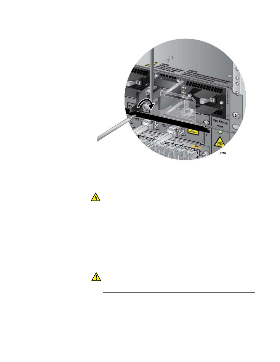
Figure 144. Connecting the Negative Lead Wire
Allied Telesis recommends tightening the screw to 30 to 40 inch-lbs.
Warning
Check to see if there are any exposed copper strands coming from
the installed wires. When this installation is done correctly there
should be no exposed copper wire strands extending from the
terminal block. Any exposed wiring can conduct harmful levels of
electricity to persons touching the wires. E12
7. Slide the plastic cover to the left and lightly tighten the two screws with
a #1 Phillips-head screwdriver to secure the cover. See Figure 133 on
page 179. You might need to lift the locking handle slightly to access
the bottom screw.
Caution
Do not over tighten the screws or you may crack or break the plastic
cover.
8. With a #2 Phillips-head screwdriver, tighten the handle locking screw
to secure the power supply to the chassis. See Figure 134 on page
180.
- AT-GS908M (54 pages)
- AT-x230-10GP (80 pages)
- AT-GS950/10PS (386 pages)
- AT-GS950/48PS (64 pages)
- AT-GS950/16PS (386 pages)
- AT-GS950/48PS (386 pages)
- AT-9000 Series (258 pages)
- AT-9000 Series (1480 pages)
- IE200 Series (70 pages)
- AT-GS950/48 (410 pages)
- AT-GS950/8 (52 pages)
- AT-GS950/48 (378 pages)
- AT-GS950/48 (60 pages)
- SwitchBlade x8112 (322 pages)
- SwitchBlade x8106 (322 pages)
- SwitchBlade x8106 (240 pages)
- SwitchBlade x8112 (240 pages)
- AT-TQ Series (172 pages)
- AlliedWare Plus Operating System Version 5.4.4C (x310-26FT,x310-26FP,x310-50FT,x310-50FP) (2220 pages)
- FS970M Series (106 pages)
- 8100L Series (116 pages)
- 8100S Series (140 pages)
- x310 Series (116 pages)
- x310 Series (120 pages)
- AT-GS950/24 (404 pages)
- AT-GS950/24 (366 pages)
- AT-GS950/16 (44 pages)
- AT-GS950/16 (364 pages)
- AT-GS950/16 (404 pages)
- AT-GS950/8 (404 pages)
- AT-GS950/8 (364 pages)
- AT-GS950/8 (52 pages)
- AT-8100 Series (1962 pages)
- AT-8100 Series (330 pages)
- AT-FS970M Series (330 pages)
- AT-FS970M Series (1938 pages)
- SwitchBlade x3106 (288 pages)
- SwitchBlade x3112 (294 pages)
- SwitchBlade x3112 (222 pages)
- AT-S95 CLI (AT-8000GS Series) (397 pages)
- AT-S94 CLI (AT-8000S Series) (402 pages)
- AT-IMC1000T/SFP (23 pages)
- AT-IMC1000TP/SFP (24 pages)
- AT-SBx3106WMB (44 pages)