Allied Telesis SwitchBlade x3106 User Manual
Page 177
SwitchBlade x3106 Installation Guide
177
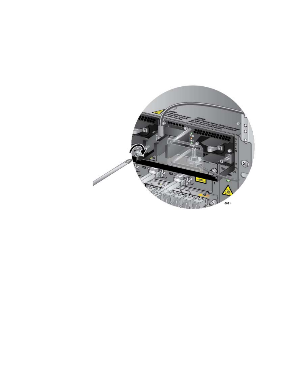
6. With a #3 Phillips-head screwdriver, connect the positive (+) power
lead wire to the positive terminal on the power supply, with one of the
terminal screws removed in the previous step. The positive terminal is
on the left. You may attach the terminals with the wires either above or
below the terminal block. Figure 131 shows the wires above the
terminal block.
Allied Telesis recommends tightening the screw to 30 to 40 inch-lbs.
Figure 131. Connecting the Positive (+) Power Wire with a Straight
Terminal
7. With a #3 Phillips-head screwdriver, connect the negative (-) power
lead wire to the negative terminal on the power supply, with the
remaining terminal screw removed in the previous step 5. The negative
terminal is on the right. You may attach the terminals with the wires
either above or below the terminal block. Figure 132 on page 178
shows the wires above the terminal block.
Allied Telesis recommends tightening the screw to 30 to 40 inch-lbs.