Input terminal, Output terminal – KYORITSU 6315 Instruction Manual User Manual
Page 129
Connection to input/ output terminals
KEW6315
127
KEW6315
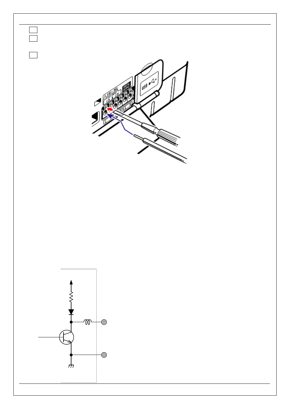
1 Open the Connector cover.
2 Press the rectangular protrusion above a terminal with a flat-blade screw driver, and insert
a signal wire.
3 Remove the driver and fix the wire.
”Input terminal”
For monitoring the voltage output signals of Thermo sensors. These terminals are useful to measure the
signals from other devices and power failures at the same time.
Number of Ch: 2ch
Input resistance : approx 225.6kΩ
”Output terminal”
For fixing the generating outputs to “Low” while power quality events are lasting. Usually, it is fixed to “High”,
but changed to “Low” if the duration of an event is less than 1 sec. This is applicable to the events with the
highest-priority only. To adjust the generating outputs to the events with low-priority, select “OFF” for the
events with higher priority than the desired event. The details are described in “Threshold setting for Power
quality (Event)” (P. 65). * [Priority order]: Transient -> INT -> Dip -> Swell -> Inrush current
Output format : Open collector output
Max input : 30V, 50mA, 200mW
Output voltage : Hi – 4 to 5V
Lo – 0 to 1V
Signal wire
+5V
H
L
OUTPUT
Flat-blade screwdriver