4 vector – KYORITSU 6315 Instruction Manual User Manual
Page 107
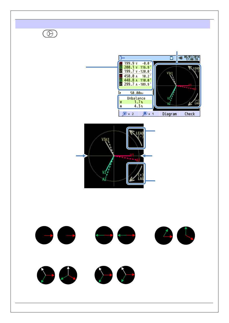
6.4 Vector
KEW6315
- 105 -
KEW6315
6.4 Vector
Press the
Key.
e.g.) 3P4W
*1
For 3P3W3A, rms line voltages are displayed.
*2
Phase angled is displayed: using Phase of V1
as the base (0
o
).
Vector display:
rms voltage (solid line)
rms current (dotted line)
The circle (solid line) represents the max values at V and A Ranges, and the line length represents rms
voltage and current values. The angle between the lines represents phase relation with reference to V1.
For 3P3W3A/3P4W, unbalance ratio is also displayed. While the measured voltages and currents are
balanced, the following vectors will be displayed.
Measured values
V: rms voltage*
1
/Phase angle*
2
A: rms current
/ Phase angle*
2
Vector display
±0°
±180°
Phase angle (Leading)
-0° to -180°
Phase angle (Lagging)
+0° to +180°
1P2W
V
A
1P3W
3P3W
±0°
±0°
1CH:±0°
2CH:±180°
1CH:±0°
2CH:±180°
1CH:±0°
2CH:-60°
1CH:-90°
2CH:+30°
3P3W3A
3P4W
1CH:±0°
2CH:+120°
3CH:-120°
1CH:+30°
2CH:+150°
3CH:-90°
1CH:±0°
2CH:+120°
3CH:-120°
1CH:±0°
2CH:+120°
3CH:-120°
V
A
V
A
V
A
V
A