2 schematic diagram of mw100 main module, Schematic diagram of mw100 main module -2, Element assembly – Yokogawa PC-Based MX100 User Manual
Page 95
5-2
SM MX100-01E
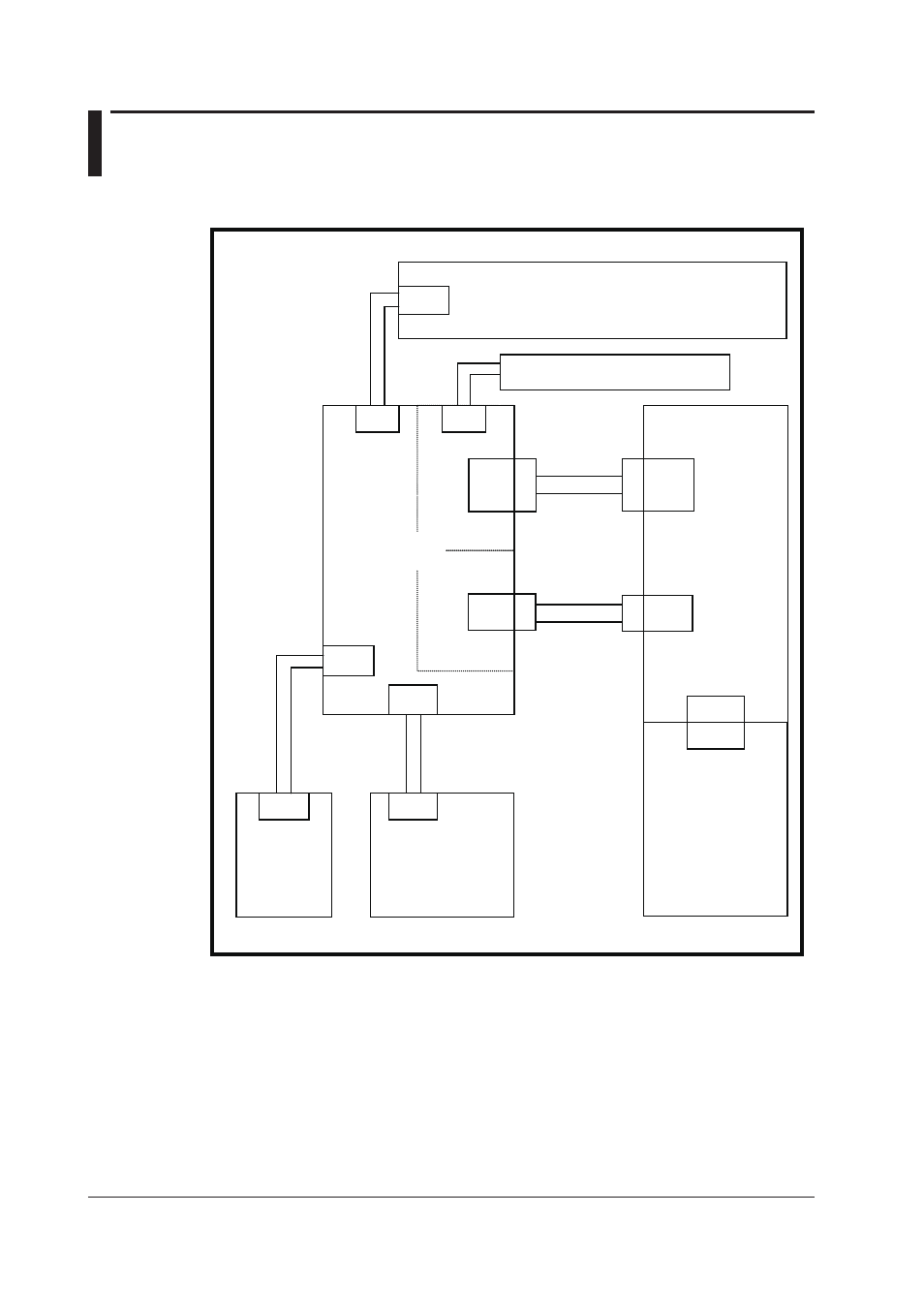
5.2 Schematic Diagram of MW100 Main Module
Wire Assembly
B8722ZA
Power Assembly
Element Assembly
TB2
TB1
TB3
CN1
Inlet
or
Power Screw
Board Assembly
Wire Assembly
for
Frequency
SUMICARD
for
RS232C/RS422
Display Board Assembly B8724TD
SUMICARD
B8724ZE
(CPU)
CN11
CN2
(Memory)
CN2
(Driver)
Serial
Communication
Board
Assembly
CN1
External
Board
Assembly
B8724TG
CN1
CN1
Battery Assembly B9900BR
SUMICARD
B8724ZC
CN12
CN11
CN1
CPU
Assembly
This manual is related to the following products:
See also other documents in the category Yokogawa Sensors:
- EJA130A (4 pages)
- EJA120A (31 pages)
- EJA130A (47 pages)
- EJA120A (40 pages)
- EJA438 (5 pages)
- EJA120A (6 pages)
- EJA115 (85 pages)
- EJA120A (47 pages)
- EJA120A (79 pages)
- EJA130A (2 pages)
- EJA210A (70 pages)
- EJA430A (78 pages)
- EJA130A (4 pages)
- EJX120A (4 pages)
- EJA210E (9 pages)
- EJX115A (55 pages)
- EJA210E (41 pages)
- EJA210E (96 pages)
- EJA210E (52 pages)
- EJA210E (89 pages)
- EJA210E (170 pages)
- FlowNavigator Software (163 pages)
- EJX910A (55 pages)
- EJX910A (175 pages)
- EJX910A (83 pages)
- EJX910A (9 pages)
- EJX910A (103 pages)
- EJA530A (67 pages)
- EJA120A (83 pages)
- EJX530A (52 pages)
- EJA110E (4 pages)
- EJA110E (85 pages)
- EJX120A (85 pages)
- EJA118 (76 pages)
- EJX118A (64 pages)
- EJA438 (72 pages)
- EJA430E (85 pages)
- EJA430E (7 pages)
- EJX430A (6 pages)
- EJX430A (40 pages)
- EJX430A (76 pages)
- EJA430E (41 pages)
- EJA430E (96 pages)
- EJX438A (10 pages)
- ADMAG AXR (194 pages)