Measurement conditions, Connection, Testing – Yokogawa PC-Based MX100 User Manual
Page 60: Wiring diagram for the -b12 and -b35 modules
2-31
SM MX100-01E
Testing
1
2
3
4
5
6
7
2.7.6
Measurement Accuracy Test
Measurement Conditions
• Measured CH is arbitrary (CH2 recommended). Also, please remember that the
measurement accuracy test is carried out at the two measurement intervals of 100 ms
and 200 ms, and the ranges and criteria differ for each.
• Set the dip switches on the -B12 and -B35 modules for 4-gauge.
ON
1 2 3 4 5
SW1 to SW4: OFF
SW5: ON
• The duration of the measured data at the 100 ms interval should be five seconds or
more, and 10 seconds or more at 200 ms, and all measured data must be checked
against the test criteria.
• If ever a criterion is not met, the unit should be calibrated and retested.
• Before performing the measurement accuracy test, restore the initial balance values
(all measuring ranges) of the measurement channels from a PC via communication.
For instructions on restoring initial balance values through PC communication, see
the MX100 standard software user’s manual (IM MX180-01E) or the MW100 data
acquisition unit user’s manual (IM MW100-01E).
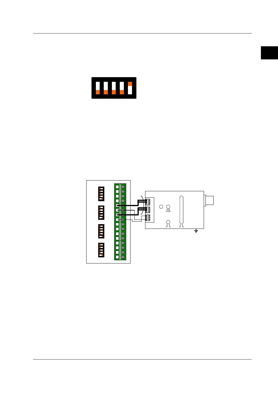
Connection
Wiring diagram for the -B12 and -B35 modules
RV1
OFF
SW8
SW7
0μSTR
P
P
PS
N
N
NS
H
-
L
-
+
OFF
ON OFF
ON
SW1
SW2
SW3
SW4
SW5
SW6
12000μSTR
30000μSTR
200000μSTR
2000μSTR
20000μSTR
10000μSTR
MX112 STRAIN CAL BOX
B8720XA
1
2
3
4
5
6
7
8
9
10
11
12
13
14
15
16
ON
1
2
3
4
5
ON
1
2
3
4
5
ON
1
2
3
4
5
ON
1
2
3
4
5
A/+V
B/ L
C/-V
D/ H
CH1
A/+V
B/ L
C/-V
D/ H
CH2
A/+V
B/ L
C/-V
D/ H
CH3
A/+V
B/ L
C/-V
D/ H
CH4
P, N line
each 10 mΩ
or less
• Because the gain error will be equal to the wiring resistance of the P and N lines,
wiring must be performed so that each wiring resistance is kept to 10 mΩ or less.
• In the figure above, two P and N lines each are connected to the Cal Box in order to
reduce wiring resistance. You do not necessarily have to connect two lines each.
2.7 Tests of the 4-CH Strain Input Module