3 excessive input test, 4 id check, Procedure – Yokogawa PC-Based MX100 User Manual
Page 45
2-16
SM MX100-01E
2.5.3
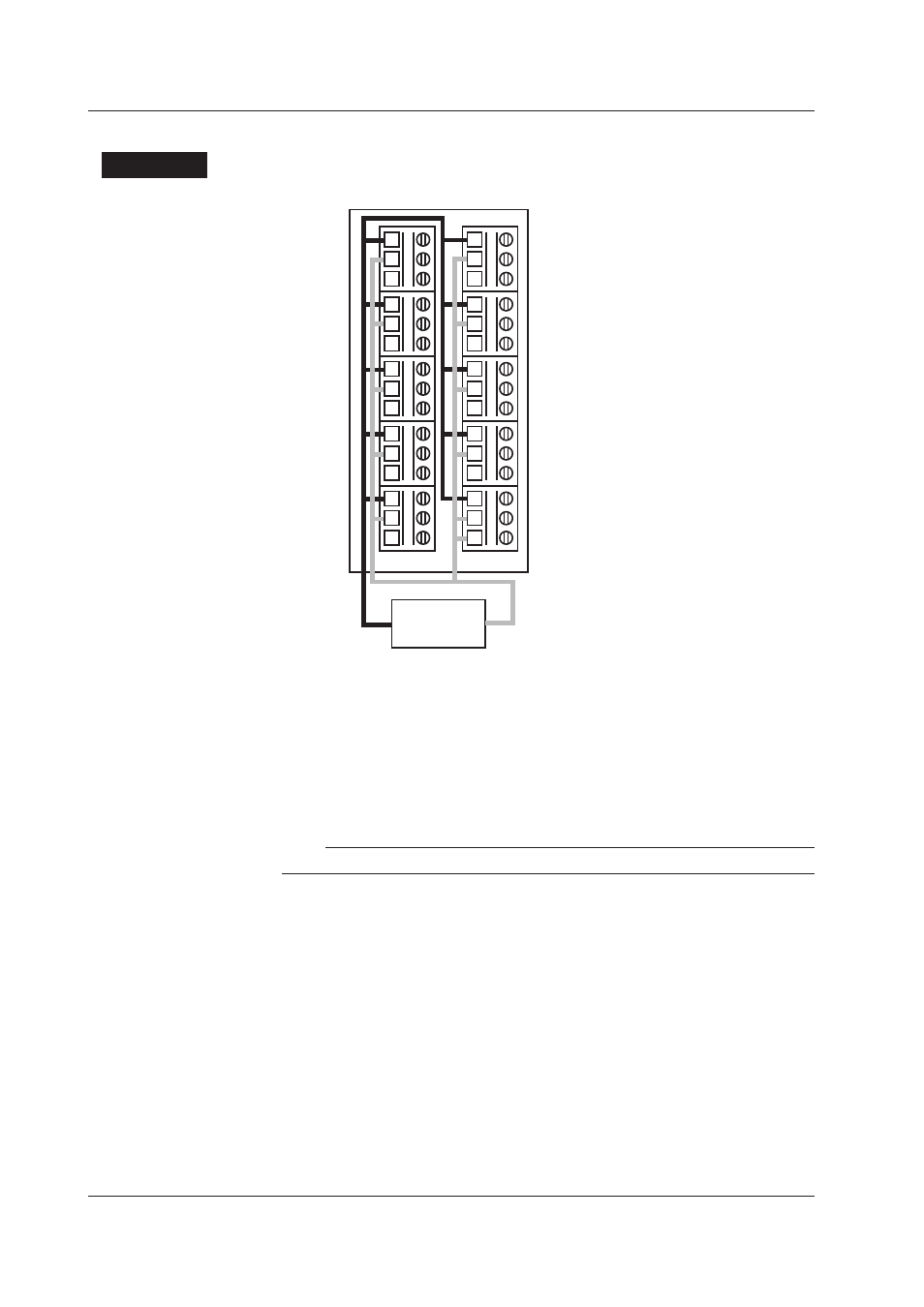
Excessive Input Test
Procedure
1.
Connect the H(A/+) side and L(B/-) side terminals separately on all channels.
+/A 1
–/B 2
b
3
+/A 1
–/B 2
b
3
+/A 1
–/B 2
b
3
+/A 1
–/B 2
b
3
+/A 1
–/B 2
b
3
+/A 1
–/B 2
b
3
+/A 1
–/B 2
b
3
+/A 1
–/B 2
b
3
+/A 1
–/B 2
b
3
+/A 1
2
b
3
Voltage
generator
1ch
2ch
3ch
4ch
5ch
6ch
7ch
8ch
9ch
10ch
–/B
2.
Set all channels to 20 mV.
3.
Input ±20 V between the H and L/b sides for 10 seconds each, and confirm that
no abnormalities
*
occur.
4.
Set all channels to the “Cu10 GE High Stability” range.
5.
Input ±10 V between the H and L/b sides for 1 minute, and confirm that no
abnormalities
*
occur.
* Abnormalities refers to excessive current or emissions of light or smoke.
Note
This test can be performed during warm-up.
2.5.4
ID Check
This test confirms whether the module and terminal board types are correctly identified
when module information is obtained from the MX100, MW100, or equivalent.
Procedure
Terminal boards B8720BE through B8720BH are exchanged one by one, and the ID is
confirmed each time a new board is installed.
When exchanging a terminal board, you must make sure that the power to the MX100,
MW100, or equivalent is turned OFF. If the OFF/ON cycle is not performed, the ID
information is not updated.
2.5 Tests of the 10-CH, Medium-Speed Universal Input Module (MX110-UNV-H10)