2 withstanding voltage test, Procedure – Yokogawa PC-Based MX100 User Manual
Page 50
2-21
SM MX100-01E
Testing
1
2
3
4
5
6
7
2.6.1
Insulation Resistance Test
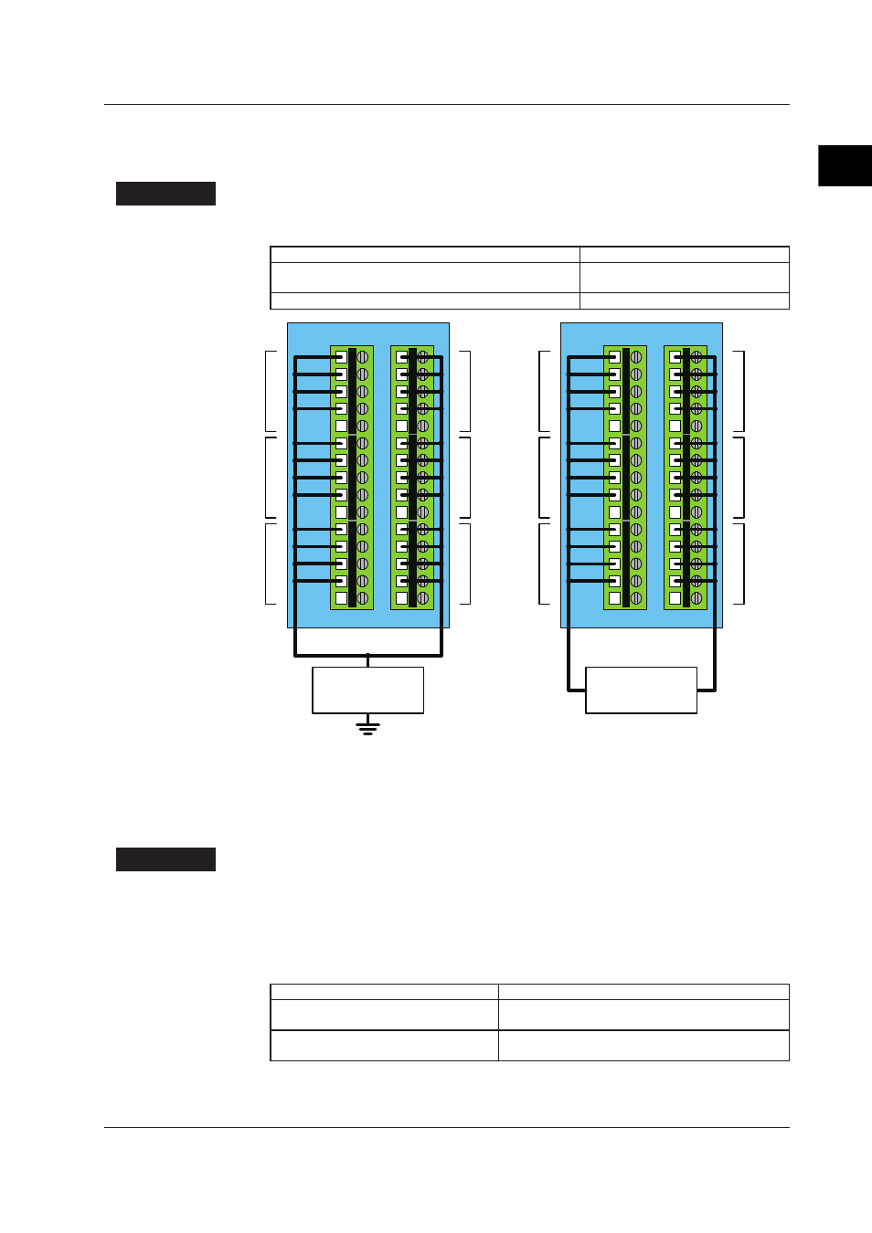
Attach the MX110 6-CH Medium-Speed Four-Wire RTD Resistance Input Module to the
MX100, MW100, or equivalent before performing this test.
Procedure
Wire the instrument as shown in the figure below, measure the insulation resistance, then
confirm that the results meet the criteria below.
Measured Item
Criteria
Input terminal to earth terminal on the MX100, MW100, or
equivalent
20 MΩ or more (at DCV 500 V)
Between input terminals
20 MΩ or more (at DCV 500 V)
1
2
3
4
5
6
7
8
9
10
11
12
13
14
15
1
2
3
4
5
6
7
8
9
10
11
12
13
14
15
/I
+/A
-/B
/C
/I
+/A
-/B
/C
/I
+/A
-/B
/C
4CH
6CH
5CH
1CH
2CH
3CH
1
2
3
4
5
6
7
8
9
10
11
12
13
14
15
1
2
3
4
5
6
7
8
9
10
11
12
13
14
15
/I
+/A
-/B
/C
/I
+/A
-/B
/C
/I
+/A
-/B
/C
4CH
6CH
5CH
1CH
2CH
3CH
Insulation resistance
tester or
Withstanding voltage
tester
Insulation resistance
tester or
Withstanding voltage
tester
Input terminal to earth terminal on the jig
Between input terminals
2.6.2
Withstanding Voltage Test
Attach the 6-CH Medium-Speed Four-Wire RTD Resistance Input Module to the MX100,
MW100, or equivalent before performing this test.
Procedure
Wire the instrument in the same manner as in section 2.6.2, “Insulation Resistance Test,”
then confirm that the results satisfy the criteria below.
For the withstanding voltage test, in order to ensure continuity from the MX100, MW100,
or equivalent’s earth to the module’s heat sink, you must fasten the module with screws
after installing it onto the base plate.
Measured Item
Criteria
Input terminal to earth terminal on the
MX100, MW100, or equivalent
Current leakage of 2 mA or less at 3700 Vrms AC for 1
minute
Between input terminals
Current leakage of 1 mA or less at 1000 Vrms AC for 1
minute
When applying voltages, ensure that the rising and falling times are both at least five
seconds.
2.6 Tests of the 6-CH, Medium-Speed Four-Wire RTD Resistance Input Module (MX110-V4R-M06)