Chapter 5 schematic diagram, 1 schematic diagram of mx100 main module, Schematic diagram of mx100 main module -1 – Yokogawa PC-Based MX100 User Manual
Page 94
5-1
SM MX100-01E
Schematic Diagram
1
2
3
4
5
6
7
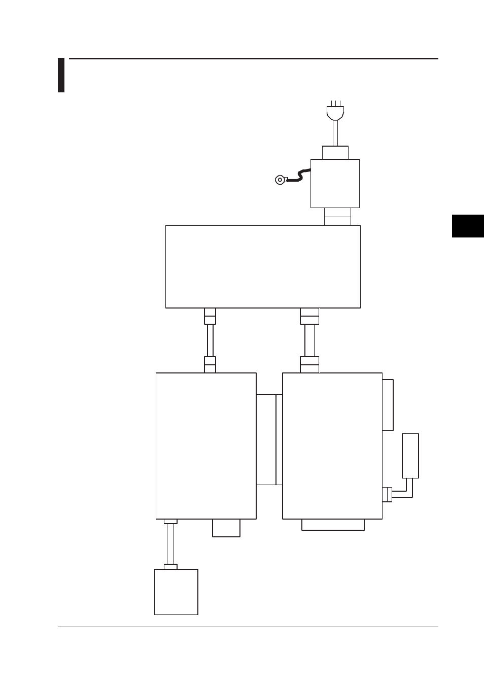
5.1 Schematic Diagram of MX100 Main Module
CPU Board B8722T
A
Memory Board
B8722TB
CN1
Ethernet
CN3
CN4
CN2
CN5
CN2
CN4
CN1
CN3
CF Card
Slot
Display Board
B8722TC
CN1
Battery
Assembly
B9900BR
W
ire
Assembly
B8722ZA
W
ire
Assembly
B8722ZB
SumiCard B8722ZC
Main Power
Assembly
B8724ZA
TB1
TB2
TB3
Frequency
DC12V
AC100 to 240V
CN1
CN2
To Base Plate
*
To protective earth
* Use one of the following assemblies according to the specifications. Power supply screw terminal MX100-
□-
□-
W Power Screw Board B8722TE
Other Inlet Board B8722TD
Chapter 5
Schematic Diagram
This manual is related to the following products: