Yokogawa PC-Based MX100 User Manual
Page 78
2-49
SM MX100-01E
Testing
1
2
3
4
5
6
7
2.10.7 Power ON Output Value Setting
Wire the units in the same manner as in the “Pulse Interval Accuracy Test,” enter all
settings (PWM output settings), then confirm that the criteria are met.
The wiring diagram for the pulse interval accuracy test shows an example of wiring CH5.
Actual measurment should be performed on all channels.
Use an external power supply of 5 V, and load resistance of 100 Ω.
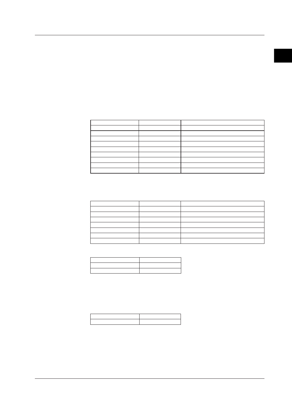
PWM Outupt Settings
Connect to the PC, then enter the following settings using the MX100 standard software.
When using the MX100/DARWIN API for settings, enter settings that are equivalent to
the following.
Item
Setting
Remarks
Enable/disable
Enabled
Select the source action
User output
Span
Need not specify
Output upon power ON
Preset value
Sets the output at power ON as a preset value.
Output upon error
Preset value
Sets the output upon error as a preset value.
Preset value
50.000 %
Set 50% duty.
Resolution
1 ms
Pulse interval
200 ms
Other settings
Not required
Using the MW100 user’s manual or communication commands, power cycle the MW100
main unit or equivalent, then measure the output on all channels.
Item
Setting
Remarks
Output type
PWM
Output method
COM
Command output
Output range
1 ms
Span
Need not specify
Pulse interval
200
Preset value
50.000 %
Set 50% duty.
Reference channel
Not required
Output Operation Setting
Item
Setting
Power ON
PRESET
Error occurence
PRESET
Criteria (for the MX100 and MW100)
Power cycle the MX100 main unit or equivalent, then measure the output values without
entering any settings using the PC.
Use a trigger level of 2.5 V. In this case, confirm that the output voltages of all channels
are within the allowable ranges.
Pulse Interval
Pulse Duty
200 ms ±16S
Duty 50% ±0.003%
2.10 8-CH, Medium-Speed PWM Output Module