5 pulse interval accuracy test, Mw100 settings – Yokogawa PC-Based MX100 User Manual
Page 75
2-46
SM MX100-01E
Referring to the MW100 user’s manual for browser operations, or by using
communication commands, power cycle the MW100 main unit or equivalent, then
measure the output on all channels.
Output Range Settings
Item
Setting
Remarks
Output type
PWM
Output method
COM
Command output
Output range
1 ms
Span
Need not specify
Pulse interval
10
Preset value
0.000%
Duty 0%
Reference channel
Not required
Output Operation Setting
Item
Setting
Power ON
PRESET
Error occurence
PRESET
Criteria (for the MX100 and MW100)
PWM Output Setting
Criteria
100.0 %
3.8 V or more
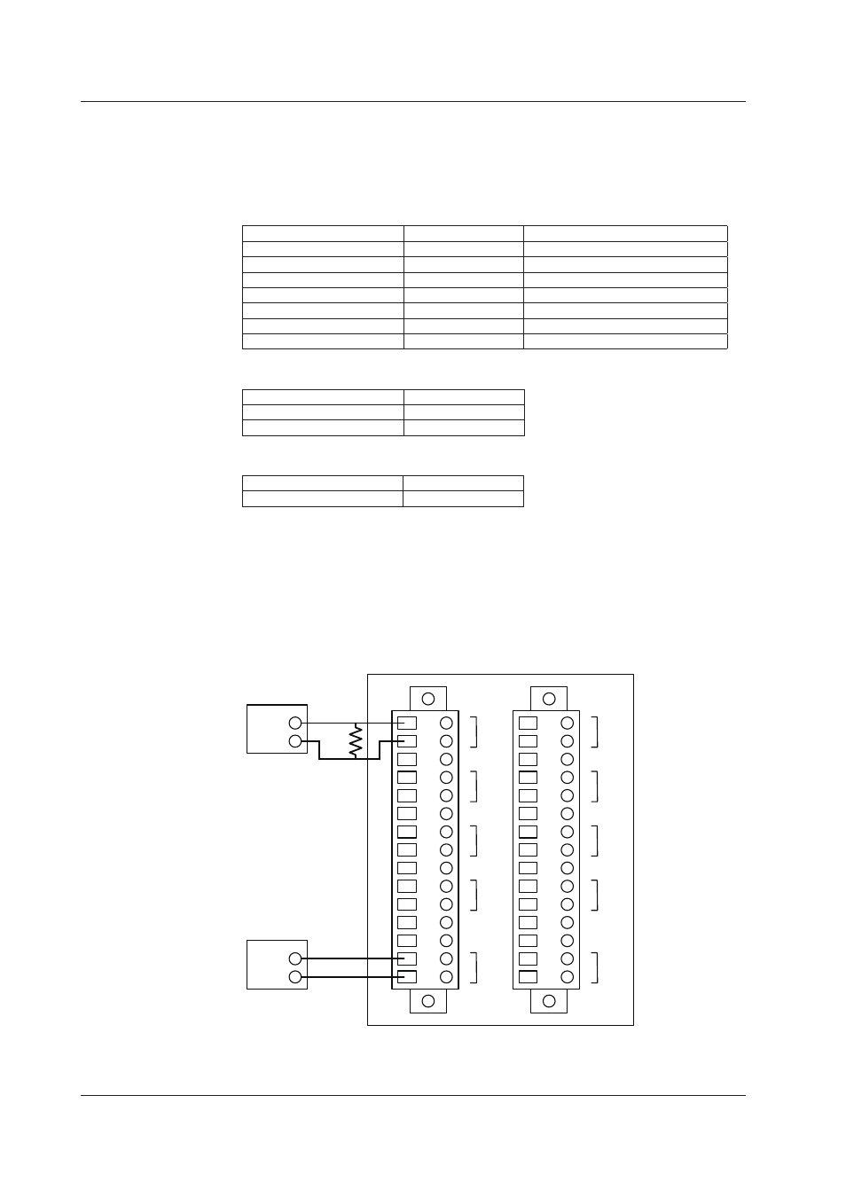
2.10.5 Pulse Interval Accuracy Test
Wire the units as in the figure below, enter all settings (PWM output settings), then
confirm that the criteria are met.
The figure below shows an example of wiring CH5. Actual measurment should be
performed on all channels.
Use an external power supply of 5 V, load resistance of 100 Ω, and a counter trigger level
of 2.5 V.
1
2
3
4
5
6
7
8
9
10
11
12
13
14
15
1
2
3
4
5
6
7
8
9
10
11
12
13
14
15
+
-
100Ω
Counter +
-
5V
V+
-
5Ch
V+
-
6Ch
V+
-
7Ch
V+
-
8Ch
+
-
Vext
+
-
Vext
V+
-
4Ch
V+
-
3Ch
V+
-
2Ch
V+
-
1Ch
Puls interval check and puls duty check wiring diagram
DC
Power
supply
2.10 8-CH, Medium-Speed PWM Output Module