1 protective ground continuity test, 2 insulating resistance test, 3 withstanding voltage test – Yokogawa PC-Based MX100 User Manual
Page 35: Procedure
2-6
SM MX100-01E
2.3.1
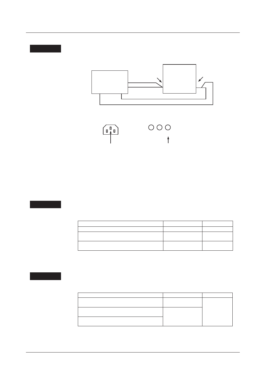
Protective Ground Continuity Test
Procedure
1.
Wire the instruments as shown below.
I–
V–
I+
V+
Earth continuity
tester
Protective earth
terminal
MW100
(main unit)
Functional
earth terminal
Protective ground terminal
L
N
G
When using an inlet
When using a screw terminal
Center pin
Right-most pin
2.
Measure the resistance between the protective ground terminal and functional
ground terminal. Use 4 wires for this measurement.
Items to Be Checked
That the resistance value does not exceed 0.1 Ω when tested at 60 Hz, 30 A for
10 seconds.
2.3.2
Insulating Resistance Test
Procedure
Perform a test using a DC 500 V insulation resistance tester and confirm that the
following criteria are met.
Terminals Measured
Power Switch
Criteria
Power terminal to functional ground terminal*
ON
20 MΩ or higher
MW100 AC power supply specifications
(short between L and N)
MW100 DC power supply specifications
(short +)
* You may use the functional ground terminal as a protective ground terminal.
2.3.3
Withstanding Voltage Test
Procedure
Perform the withstanding voltage test, and confirm that the following criteria are met and
that no abnormalities occur.
Terminals Measured
Power Switch
Criteria
AC power supply terminal to functional ground
terminal*
ON
1.5 kVAC for 1
minute
MW100 AC power supply specifications
(short between L and N)
Leakage current of 5
mA or less
MW100 DC power supply specifications
(short +)
* You may use the functional ground terminal as a protective ground terminal.
2.3 Tests of the MW100 Main Module