5 output accuracy test – Yokogawa PC-Based MX100 User Manual
Page 69
2-40
SM MX100-01E
1.
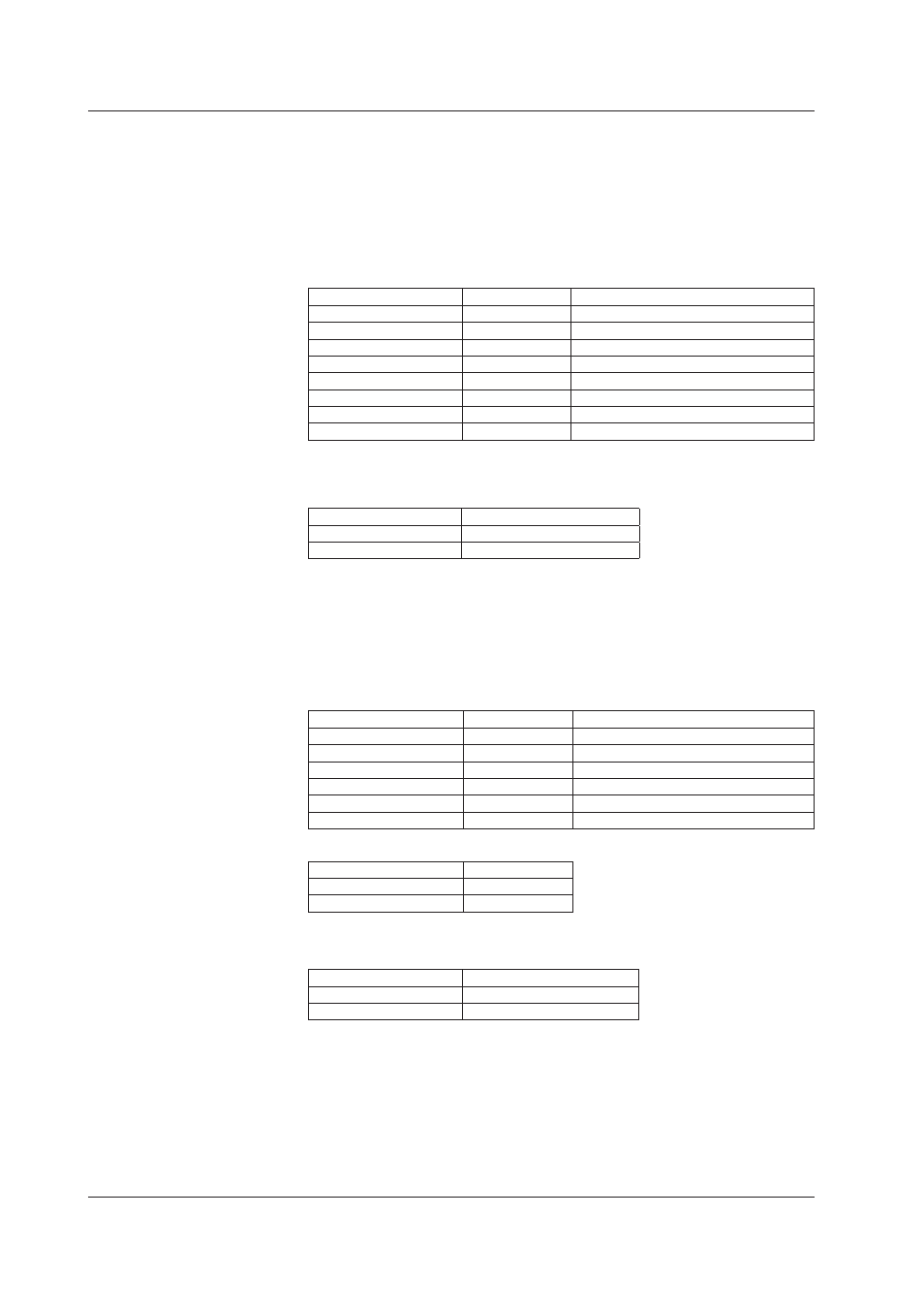
Enter settings in the table below to specify output at power ON using the MX100
standard software or the MX100/DARWIN API. Power cycle the MX100 main
unit or equivalent, then measure the output on all channels. (Without PC
communications.)
Enter the same settings on all channels.
When using the API for settings, enter settings that are equivalent to the following.
Item
Setting
Description/Notes
Enable/disable
Enabled
Action
User output
Voltage/current
Voltage
Span
Need not specify -10–10 V
Output upon power ON
Preset value
Sets the power ON operation as the preset.
Output upon error
Preset value
Sets the output upon error as the preset.
Preset value
+11 V
Sets +11 V as the preset value.
Other
Not required
2
Confirm that the output voltages of all channels are within the allowable ranges
shown below.
Output Terminal
Allowable Range
Voltage
11 V ±32 mV
Current
22 mA–24.6 mA
1.
Referring to the MW100 user’s manual for browser operation, or by using
communication commands, set the output at power ON according to the table
below. Power cycle the MW100 main unit or equivalent, then measure the output
on all channels.
Output Range Settings
Item
Setting
Description/Notes
Output Type
AO
Output method
COM
Command output
Output range
10 V
Span
Need not specify -10–10 V
Preset value
+11 V
Reference channel
Need not specify
Output Operation Setting
Item
Setting
Power ON
PRESET
Error occurence
PRESET
2
Confirm that the output voltages of all channels are within the allowable ranges
shown below.
Output terminal
Allowable Range
Voltage
11 V ±32 mV
Current
22 mA – 24.6 mA
2.9.5
Output Accuracy Test
Measurement Conditions
After calibration, if you do not turn OFF the power at least once, even if you perform
measurement correctly the calibration data may not be recorded accurately. Therefore,
power cycle the unit before performing the test.
Perform measurement on all channels.
2.9 Tests of the 8-CH Analog Output Module