6 between-channel error test, 7 burnout test, Procedure – Yokogawa PC-Based MX100 User Manual
Page 47
2-18
SM MX100-01E
2.5.6
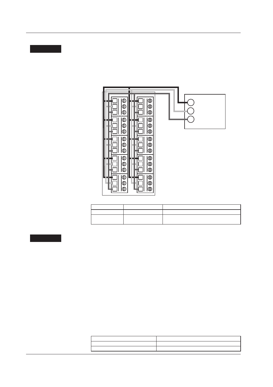
Between-Channel Error Test
Procedure
1.
Connect the H(A/+) side and L(B/-) side on all channels as shown in the figure below.
When connecting, do not bundle the wires on the input terminal side, but rather
near the voltage generator or resistor. Also, ensure that the resistance vales of all
three wires connected to each channel are equal. Otherwise, measurement errors
will occur.
1
2
3
1ch
1
2
3
2ch
1
2
3
3ch
1
2
3
4ch
1
2
3
1
2
3
1
2
3
1
2
3
1
2
3
1
2
3
5ch
6ch
7ch
8ch
9ch
10ch
–/B
+/A
b
+/A
–/B
b
+/A
–/B
b
+/A
–/B
b
+/A
–/B
b
+/A
–/B
b
+/A
–/B
b
+/A
–/B
b
+/A
–/B
b
+/A
–/B
b
+/A
–/B
b
Voltage
generator
Variable
resistor
2.
Confirm that the between-channel error vales are less than the criteria given below.
Range
Input
Criteria
20 mV
Short input H to L
0.000 mV ± 4 digits
Cu10 GE
9.036 Ω
Between-channel dispersion: 1.2°C
Measured value: 0±1.6°C (all channels)
2.5.7
Burnout Test
Procedure
1.
Connect 2 kΩ and (200 kΩ + 0.22 µF) pararel junction between H(A/+) and L(B/-)
on any two channels.
2.
Enter the following measurement ranges on the MX100/MW100.
Type-K thermocouple
Burnout ON
3.
Confirm that the measured results match the table below.
4.
Set the measurement range to “B/O OFF,” and confirm that the measured values
do not max out.
5.
Remove the 2 kΩ resistor in step 1, and connect a load (200 kΩ + 0.22 µF) in parallel.
6.
Enter the following measurement range on the MX100/MW100.
Type-K thermocouple
Burnout ON
7.
Confirm that the measured results match the list below.
8.
Set the measurement range to “B/O OFF” and confirm that the measured values
do not max out.
Connected Load
Measured Result
2 kΩ
Near Room Temperature
200 kΩ + 0.22 µF wired in parallel
Detection of an overrange or burnout
2.5 Tests of the 10-CH, Medium-Speed Universal Input Module (MX110-UNV-H10)