Yokogawa PC-Based MX100 User Manual
Page 70
2-41
SM MX100-01E
Testing
1
2
3
4
5
6
7
Connection
Wire the units in the same manner as in the “Output at Power ON Check.”
Settings
Set one channel at a time, setting the output of channels not under test to 0 V.
When using the MX100/DARWIN API for settings, enter settings that are equivalent to
the following.
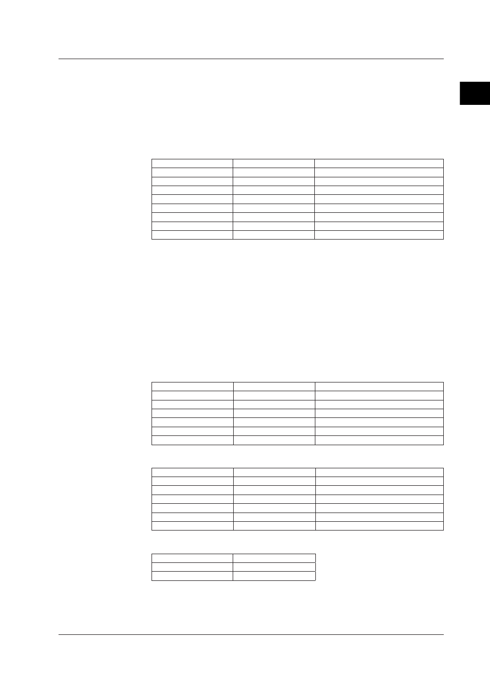
Item
Setting
Description/Notes
Enable/disable
Enabled
Action
User output
Voltage/current
Voltage
Not relevant when using the API
Span
Need not specify
-10–10 V is acceptable.
Output upon power ON
Preset value
Sets the power ON operation as the preset.
Output upon error
Preset value
Sets the output upon error as the preset.
Preset value
+0 V
Sets +0 V as the preset value.
Other
Not required
The relationship between output values of voltage and current on the same channel are
as follows.
• 1 V 4 mA
• 5 V 20 mA
Therefore, you can check the output accuracy of voltage and current simultaneously with
one setup.
Referring to the MW100 user’s manual for browser operation, or by using communication
commands, , set the output at power ON according to the table below. Power cycle the
MW100 main unit or equivalent, then measure the output on all channels.
For voltage of output range
Item
Setting
Description/Notes
Output Type
AO
Output method
COM
Command output
Output range
10 V
Span
Need not specify
-10 to 10 V
Preset value
0 V
Reference channel
Not required
For current of output range
Item
Setting
Description/Notes
Output Type
AO
Output method
COM
Command output
Output range
20 mA
Span
Need not specify
0 to 20 mA
Preset value
+10 mA
Reference channel
Not required
Output Operation Setting
Item
Setting
Power ON
PRESET
Error occurence
PRESET
2.9 Tests of the 8-CH Analog Output Module