3 id check, 4 power on output check – Yokogawa PC-Based MX100 User Manual
Page 68
2-39
SM MX100-01E
Testing
1
2
3
4
5
6
7
2.9.2
Withstanding Voltage Test
Install the module under test in the MX110, MW100, or equivalent before performing this
test.
When applying voltages, ensure that the rising and falling times are both at least five
seconds.
Wire the instrument in the same manner as in the insulation resistance test, then confirm
that the results satisfy the criteria below.
Terminals Measured
Criteria
Output terminal to earth terminal on the MX100,
MW100, or equivalent
AC2300 Vrms for 1 minute, with current
leakage of 2 mA or less
2.9.3
ID Check
This test confirms whether the module is correctly identified when module information is
obtained from the MX100, MW100, or equivalent.
(If the OFF/ON cycle is not performed on the MX100, MW100, or equivalent, the ID
information is not updated.)
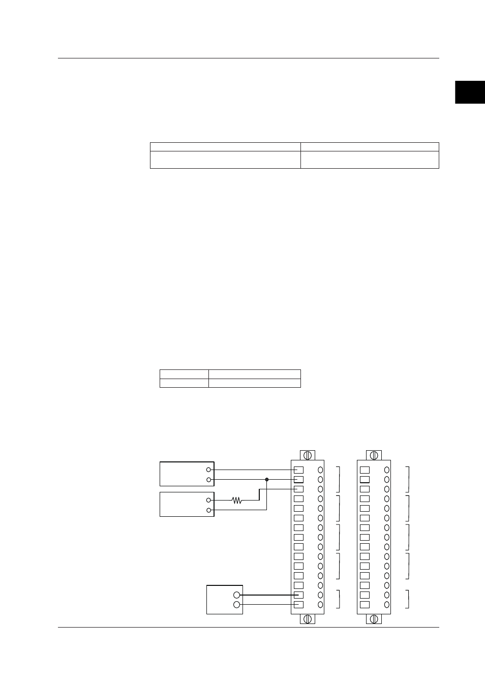
2.9.4
Power ON Output Check
Wire the units as shown in the connection diagram, then perform the power ON output
check. The figure below shows an example of wiring for measurement on CH5. Connect
other channel in the same manner and perform measurement.
Precautions to Be Taken When Connecting Cables
▪ For current measurements, connect 600 Ω series resistance as shown in the figure
below before taking measurements.
When using a DMM whose current measuring range is of a large internal resistance,
adjust the external resistance value so that the total resistance is 600 Ω.
Recommended test instruments The internal resistance of the Agilent 3458A is as
follows.
Range
Shunt Resistor
100 mA 1 Ω
▪ Connect the external power supply (24 V ±10) to the Vext terminal as in the figure
below.
The Vext terminals of the left and right connectors are connected inside the module,
therefore the power must only be connected to one of the terminals. Do not connect to
both terminals.
DMM +
-
1
2
3
4
5
6
7
8
9
10
11
12
13
14
15
1
2
3
4
5
6
7
8
9
10
11
12
13
14
15
V+
-
I+
V+
-
I+
V+
-
I+
V+
-
I+
V+
-
I+
V+
-
I+
V+
-
I+
V+
-
I+
CH1
CH2
CH3
CH4
CH5
CH6
CH7
CH8
+
-
+
-
Vext
Vext
DMM +
-
+
-
DC power supply
24V±10%
For voltage measurement
For current mesurement
600Ω ± 5%
2.9 Tests of the 8-CH Analog Output Module