3 tests of the mw100 main module, Tests of the mw100 main module -5, Tests – Yokogawa PC-Based MX100 User Manual
Page 34: Instruments used, Before testing, Procedures
2-5
SM MX100-01E
Testing
1
2
3
4
5
6
7
2.3 Tests of the MW100 Main Module
Tests
2.3.1 Protective Ground Continuity Test
2.3.2 Insulation Resistance Test
2.3.3 Withstanding Voltage Test
2.3.4 Power Supply Frequency Detection Function
2.3.5 Battery Backup Function
2.3.6 Module Communication Function
2.3.7 Key Switch Test
2.3.8 Serial Communication Function (with Option /C2 or /C3 Only)
Instruments Used
Instrument
Description
Insulation resistance tester
YOKOGAWA 2407 or equivalent
A device that can measure 100 MΩ or more at 500 VDC
Withstanding voltage tester
Kikusui TOS-9201 or equivalent
A device that can measure 1.5 kVAC for 1 minute with a
limit current of 10 mA
Earth continuity tester
Kikusui TOS-6200 or equivalent
AC stabilized power supply
A device capable of outputting AC100 V, and switching
between 50 and 60 Hz
DC stabilized power supply
A device capable of outputting DC12–28 V with an
output capacity of 30 W or more
Input module and base plate (for test)
PC with Internet Explorer installed, capable of performing Ethernet or RS-232 communications
RS-232/RS-422 converter or PC compatible RS422 communication module
RS-232 cross cable
Before Testing
Initialize the memory before beginning any test.
To initialize the memory, use the dip switches according to the following procedure.
Procedures
1.
Turn OFF the power to the MW100.
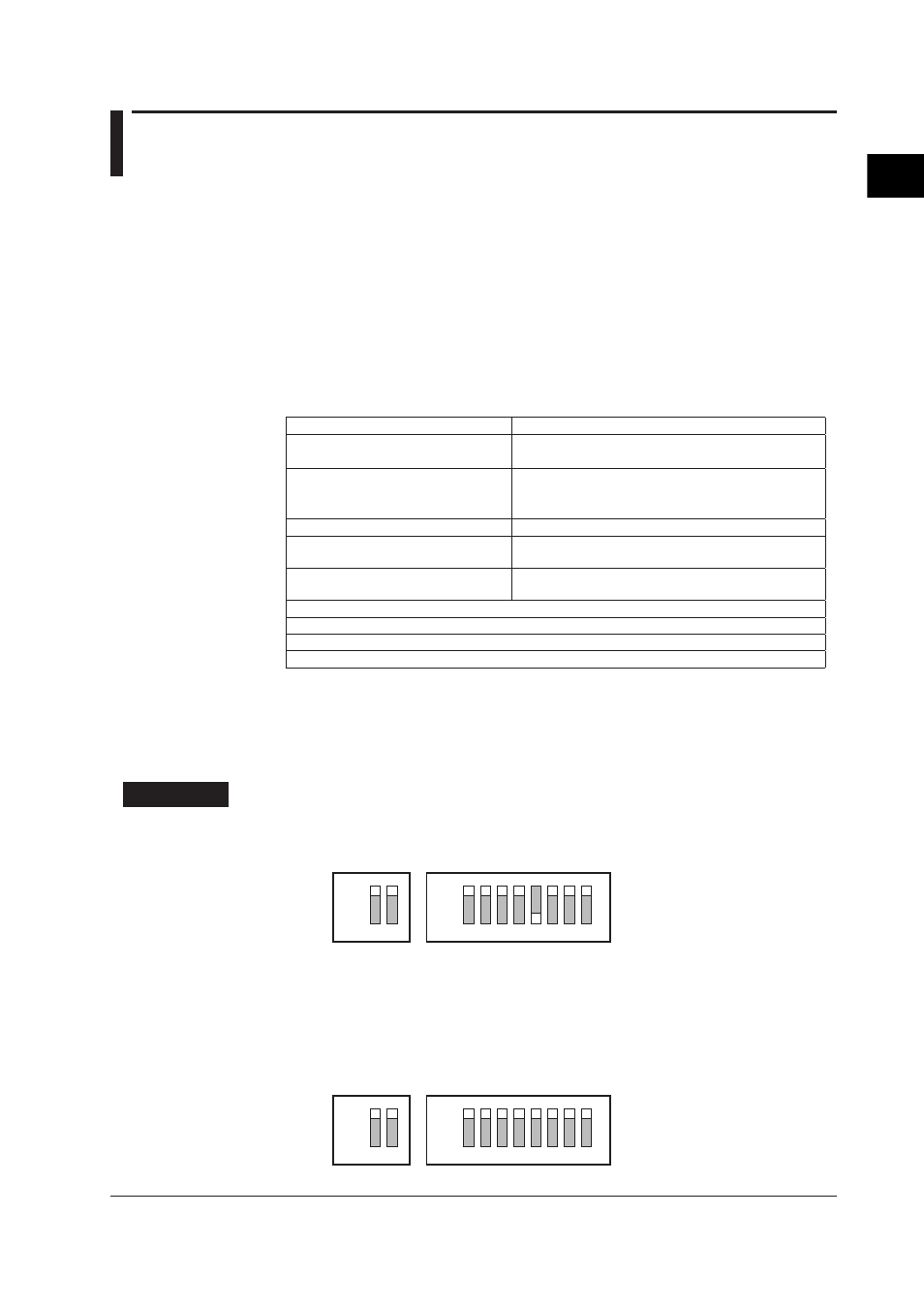
2.
Set the dip switches as shown in the figure below. (Turn SW5 OFF.)
1
2
3
4
5
6
7
8
ON
1
2
ON
3.
Turn ON the power to the MW100.
4.
Check that bF is displayed on the 7-segment LED, then turn OFF the power to the
MW100 again.
5.
Set the dip switches as shown in the figure below. (For normal operation, all
switches are turned ON.)
1
2
3
4
5
6
7
8
ON
1
2
ON