4 measurement accuracy test, Procedure – Yokogawa PC-Based MX100 User Manual
Page 40
2-11
SM MX100-01E
Testing
1
2
3
4
5
6
7
Setting All Channels to Pt100/1 mA High Resolution Range
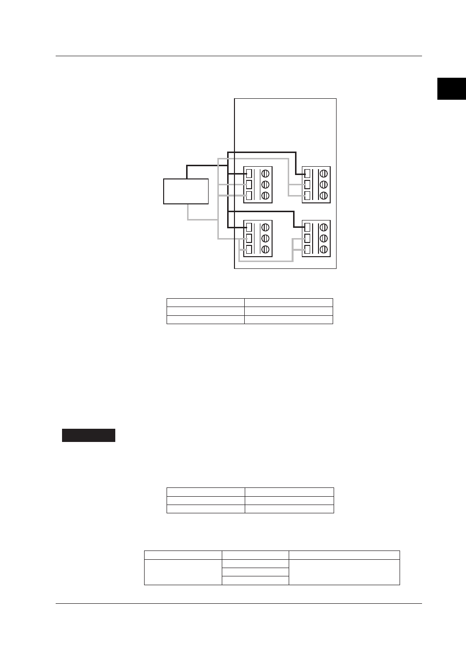
1.
Connect all A (1) and B, b (2, 2) terminals separately on channels 1 through 4 as
shown in the figure below.
A 1
B 2
b 3
3ch
A 1
B 2
b 3
1ch
A 1
B 2
b 3
4ch
A 1
B 2
b 3
2ch
DC voltage
generator
2.
Apply the voltages below between the A-B and b (1, 2, 3) terminals, and confirm
that no abnormalities occur.
Applied Voltage
Duration
+10 V
1 minute
-10 V
1 minute
2.4.4
Measurement Accuracy Test
For this test, the Four-Channel, High-Speed Universal Input Module is installed with the
MX100, MW100, or equivalent device.
Test Conditions
• After calibration, if you do not turn OFF the power, even if you perform measurement
correctly the calibration data may not be recorded accurately. Therefore, after
calibration you must turn OFF the power at least once before performing the test.
• Allow the instrument to warm up for 10 minutes at an ambient temperature of 23±5°C
and relative humidity of 55 ±20% before performing the test.
Procedure
The MX110-UNV-H04 has a separate AD for each channel, so the measurement
accuracy of each channel (1 through 4) must be confirmed.
1.
Since product specifications vary depending on the measurement interval, the
measurement accuracy test must be performed at the following two intervals.
Measurement Interval
Measuring Range
10 ms
DCV Range
50 ms
DCV, RTD Rage
2.
Confirm that the following product specifications are met (assuming measurement
of 20 data or more).
Measurement interval of 10 ms
Measuring Range
Input Value
Specification
2 V
+2.0000 V
±(0.1% of rdg + 10 digits)
0.0000 V
-2.0000 V
2.4 Tests of the 4-CH, High-Speed Universal Input Module (MX110-UNV-H04)