Yokogawa PC-Based MX100 User Manual
Page 146
7-6
SM MX100-01E
11.
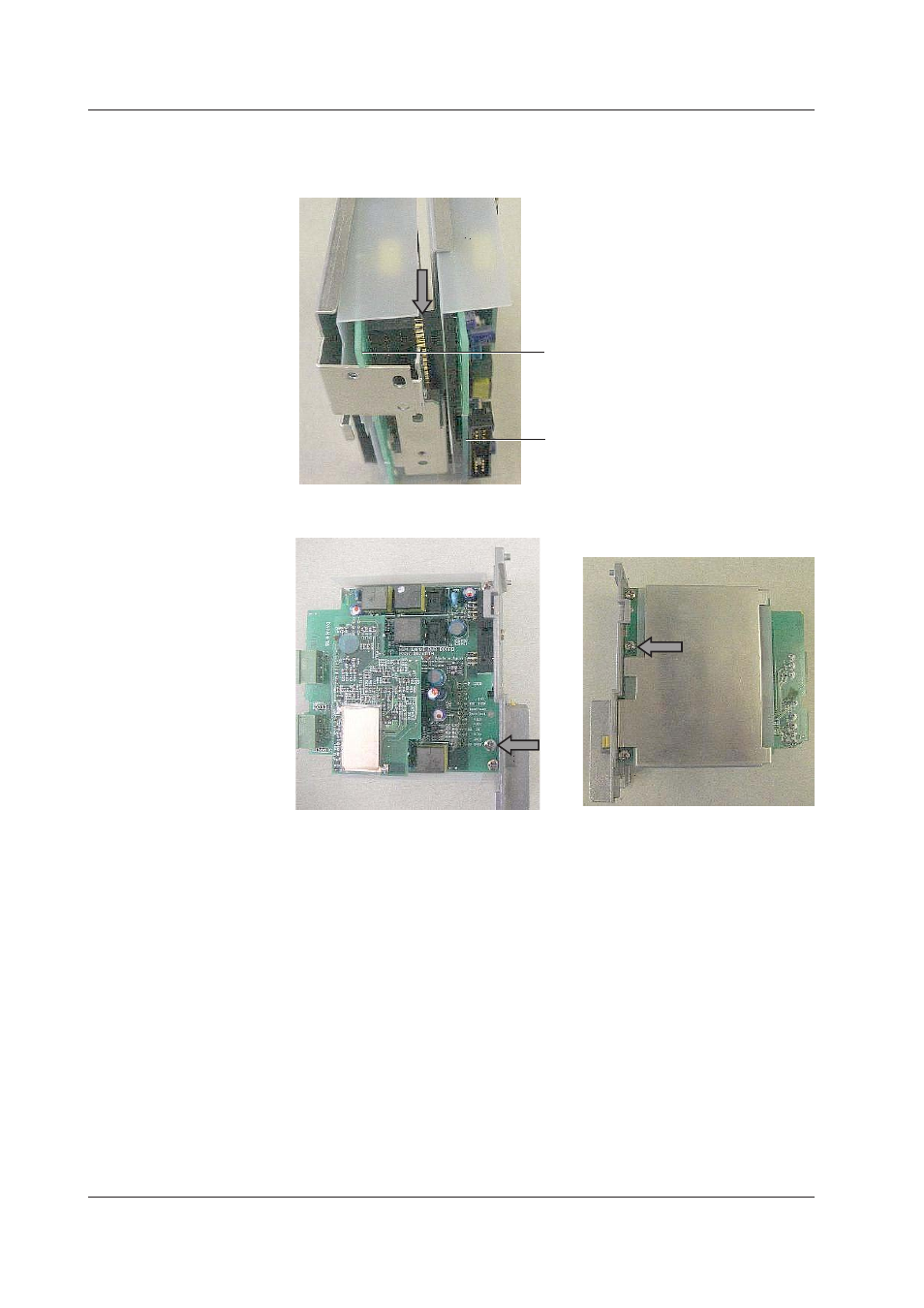
Remove the Module Back Plate.
Module Back Plate removed
(the center connectors seem to be coming free, but actually at this point they are
totally connected.)
H04 Input PWB Board
+
H04 Input AD Board
H04 Input CTRL Board
+
H04 Input AD Board
12.
Remove the two screws as indicated by the arrows in the figure below.
13.
Remove the connectors in the figure in step 11, then remove the H04 Input CTRL
Board + AD Board and the H04 Input PWR Board + AD Board.
Also remove the fittings for the H04 Input CTRL Board and the H04 Input PWR
Board. The plastic plate and H04 are affixed to the IC on the top of the board with
adhesive and cannot be removed.
7.2 Disassembling the MX110 Analog Input Module
This manual is related to the following products: