Cautions during reassembly – Yokogawa PC-Based MX100 User Manual
Page 147
7-7
SM MX100-01E
Procedures for Disassembly
1
2
3
4
5
6
7
Remove the H04 Input AD Board from the H04 Input PWR Board
14.
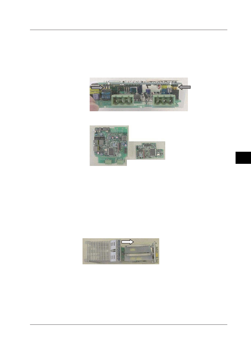
Remove the two connectors as indicated by the arrows in the figure below. In
this case, if you remove only the connectors on one side the connector pins may
bend, so you should remove the connectors on both sides simultaneously. To do
so, push the lower side of the board in the figure below, then carefully and slowly
lift both edges of the board on the upper side alternately to remove.
The H04 Input AD Board and the H04 Input PWR Board are separated.
Unit with the H04 Input AD Board from the H04 Input PWR Board removed
Remove the H04 Input AD Board from the H04 Input CTRL Board
15.
In the same manner as in step 16, remove the H04 Input AD Board from the H04
Input CTRL Board.
Cautions during Reassembly
• When reassembling the H04 Input PWR Board and the H04 Input AD Board, make
sure to correctly position the connector pins when pushing in (if you push in the boards
in the wrong position, fire can result). Take the same precautions when assembling
the H04 Input CTRL Board + AD Board and the H04 Input PWR Board + AD Board.
• When attaching the Module Case to a module, insert it as indicated by the arrows in
the figure below.
• When attaching the Bezel, ensure that the H04 RJC Board does not come loose from
its connectors.
After attaching it, examine the space for the Bezel Terminal, and check that the H04
RJC Board is connected. If not, remove the Bezel, and reattach the H04 RJC Board.
7.2 Disassembling the MX110 Analog Input Module