Tests, Instruments used, 1 insulation resistance test – Yokogawa PC-Based MX100 User Manual
Page 86: 2 withstanding voltage test, 3 id check, 4 between-channel measurement error test, 5 reference junction compensation accuracy test
2-57
SM MX100-01E
Testing
1
2
3
4
5
6
7
2.13 Tests of the Plate with Clamp Terminals
(772063)
Tests
2.13.1 Insulation Resistance Test
2.13.2 Withstanding Voltage Test
2.13.3 ID Check
2.13.4 Between-Channel Measurement Error Test
2.13.5 Reference Junction Compensation Accuracy Test
Instruments Used
Same as section 2.12, “772061 10-ch Screw Terminal Block.”
2.13.1 Insulation Resistance Test
Same as section 2.12, “772061 10-ch Screw Terminal Block.”
However, when applying voltages to input terminal to earth, do so on the MX100 or
equivalent. Also, after attaching the module to the base plate, always fasten with screws.
2.13.2 Withstanding Voltage Test
Same as section 2.12, “772061 10-ch Screw Terminal Block.”
However, when applying voltages to input terminal to earth, do so on the MX100 or
equivalent. Also, after attaching the module to the base plate, always fasten with screws.
2.13.3 ID Check
Same as section 2.12, “772061 10-ch Screw Terminal Block.”
2.13.4 Between-Channel Measurement Error Test
Same as section 2.12, “772061 10-ch Screw Terminal Block.”
2.13.5 Reference Junction Compensation Accuracy Test
Always use terminal covers.
Procedure
1.
Allow a warm-up of 30 minutes or more.
2.
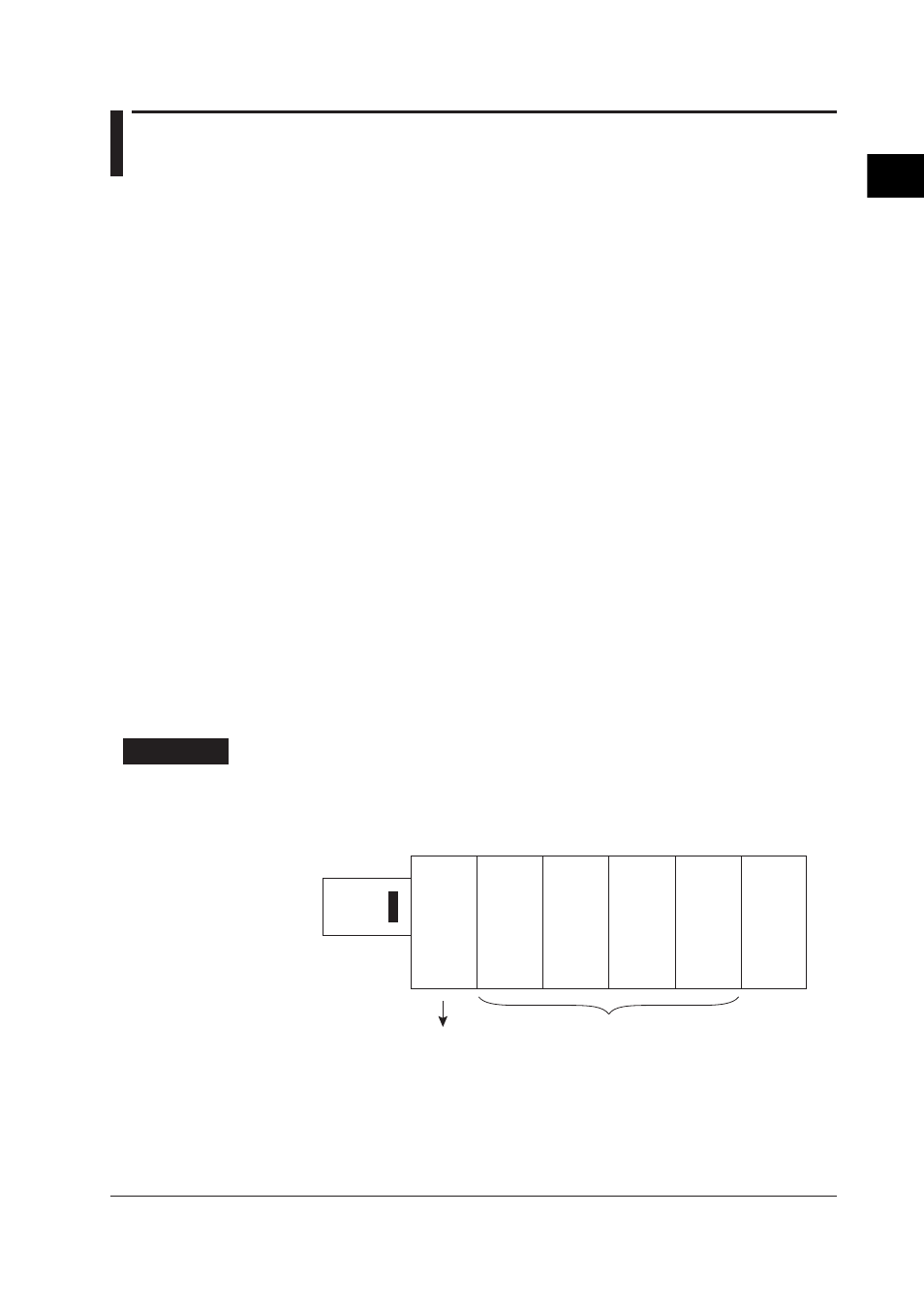
As shown in the figure below, use slots 0 through 4 and install the dummy module
in the outer-most slot.
Example: When testing 4 modules at once
MX110-U
NV-H04
MX110-
UNV-M10
MX110-
UNV-M10
MX110-
UNV-M10
MX110-
UNV-M10
MX100
or MW100
Main
Module
ASSY under test
Use an MX110-UNV-H04 as the dummy.
Module of the jig
3.
Measure the 0°C standardized temperature tank at the range for Type-T
thermocouples. Measure on channel 4, and confirm that the result lies within 0°C
± 0.5°C.