3 display input test, 4 id check – Yokogawa PC-Based MX100 User Manual
Page 66
2-37
SM MX100-01E
Testing
1
2
3
4
5
6
7
2.8.2
Withstanding Voltage Test
For this test, the Ten-Channel, High-Speed Digital Input Module is installed with the
MX100, MW100 or equivalent device.
Procedure
1.
Measure the withstanding voltage at the same locations indicated in step 1 of the
insulation resistance test. When performing the test, you must fasten the module
being tested to the MX150 base plate jig with screws.
2.
Confirm that the criterion below is met.
Input terminal to earth terminal: AC2300 Vrms for 1 minute, 2 mA or less
2.8.3
Display Input Test
For this test, the Ten-Channel, High-Speed Digital Input Module is installed with the
MX100, MW100 or equivalent device.
Procedure
1.
Allow a warm-up of 10 minutes or more.
2.
Set the measurement interval on the module being tested to 500 ms.
3.
Input DC voltage and resistance to each channel of the Ten-Channel High-Speed
Digital Input Module, and confirm each input value.
If the /NC option is installed, use B8720BF during the test.
(When the test is complete, be sure to remove the B8720BF.)
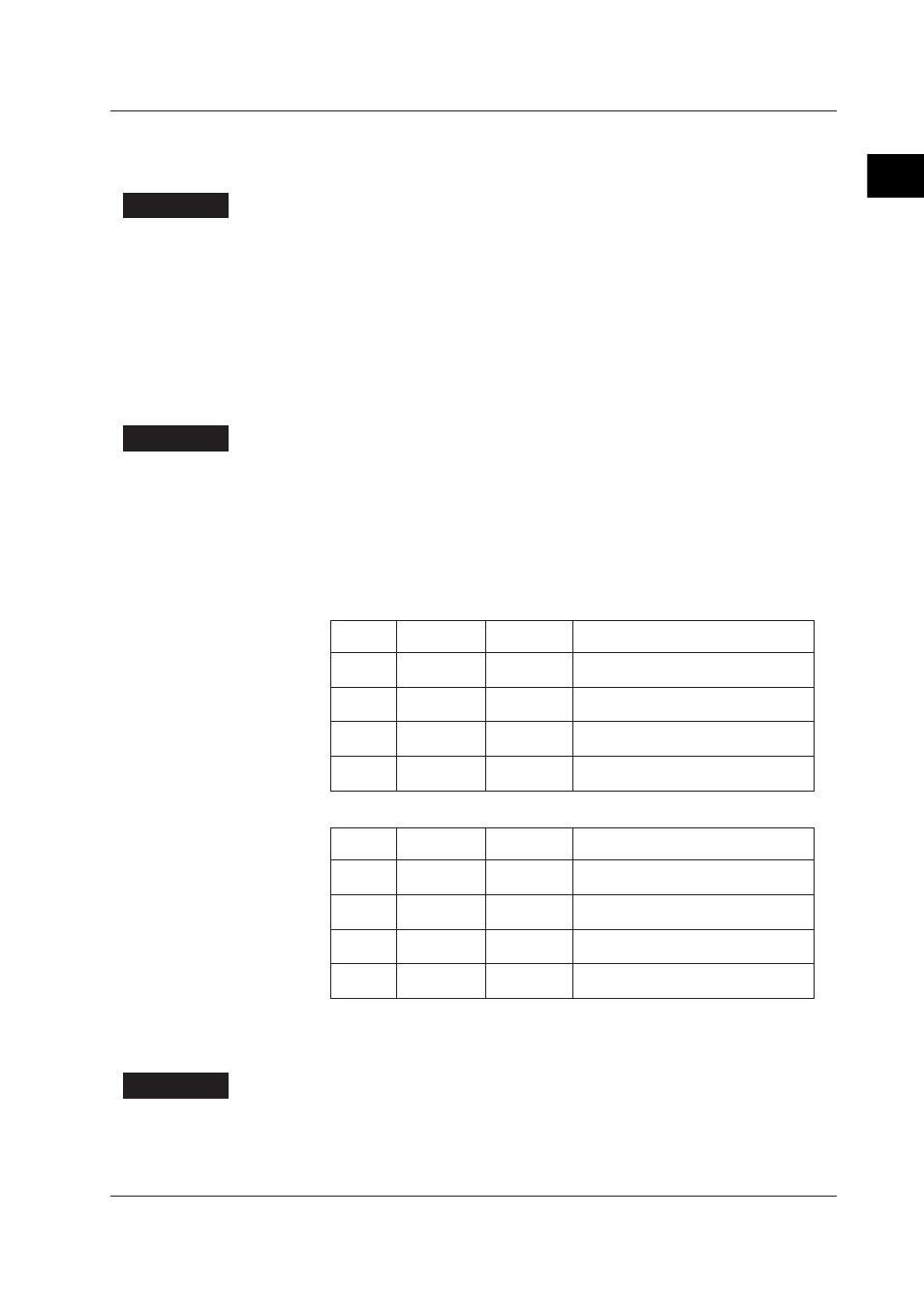
Syntax
Input Voltage,
Resistance
Measurement
Interval
Judgment Criterion
LEVEL
+1 V or less
500 ms
That the input channel reads 0
That the channels with no input read 1
LEVEL
+3 V or more 500 ms
That the input channel reads 1
That the channels with no input read 0
CONTACT 100 Ω or less 500 ms
That the input channel reads 1
That the channels with no input read 0
CONTACT 100 kΩ or
more
500 ms
That the input channel reads 0
That the channels with no input read 1
Syntax
Input Voltage,
Resistance
Measurement
Interval
Judgment Criterion
LEVEL
+6 V or less
500 ms
That the input channel reads 0
That the channels with no input read 1
LEVEL
+16 V or more 500 ms
That the input channel reads 1
That the channels with no input read 0
CONTACT 100 Ω or less 500 ms
That the input channel reads 1
That the channels with no input read 0
CONTACT 100 kΩ or
more
500 ms
That the input channel reads 0
That the channels with no input read 1
2.8.4
ID Check
This test confirms whether the module and terminal board types are correctly identified
when module information is obtained from the jig on the MX100 or equivalent.
Procedure
Exchange the terminal board from the B8720BF to a screw terminal block or equivalent,
and then check the ID before and after the new board is installed.
When exchanging a terminal board, you must make sure that the power to the MX100 or
equivalent is turned OFF.
2.8 Tests of the 10-CH, High-Speed Digital Input Module (MX115-D05-H10)