Procedure, Measurement between input terminals – Yokogawa PC-Based MX100 User Manual
Page 38
2-9
SM MX100-01E
Testing
1
2
3
4
5
6
7
2.4.1
Insulation Resistance Test
For this test, the Four-Channel, High-Speed Universal Input Module is installed with the
MX100, MW100, or equivalent. Perform this test before the test described in section 2.4.2,
“Withstanding Voltage Test.”
procedure
Wire the instrument as shown in the figure below, measure insulation resistance, then
confirm that the results meet the criteria below.
Measured Item
Criteria
Input terminal to earth terminal
DC500 V, 10 MΩ or more
Between input terminals
DC500 V, 20 MΩ or more
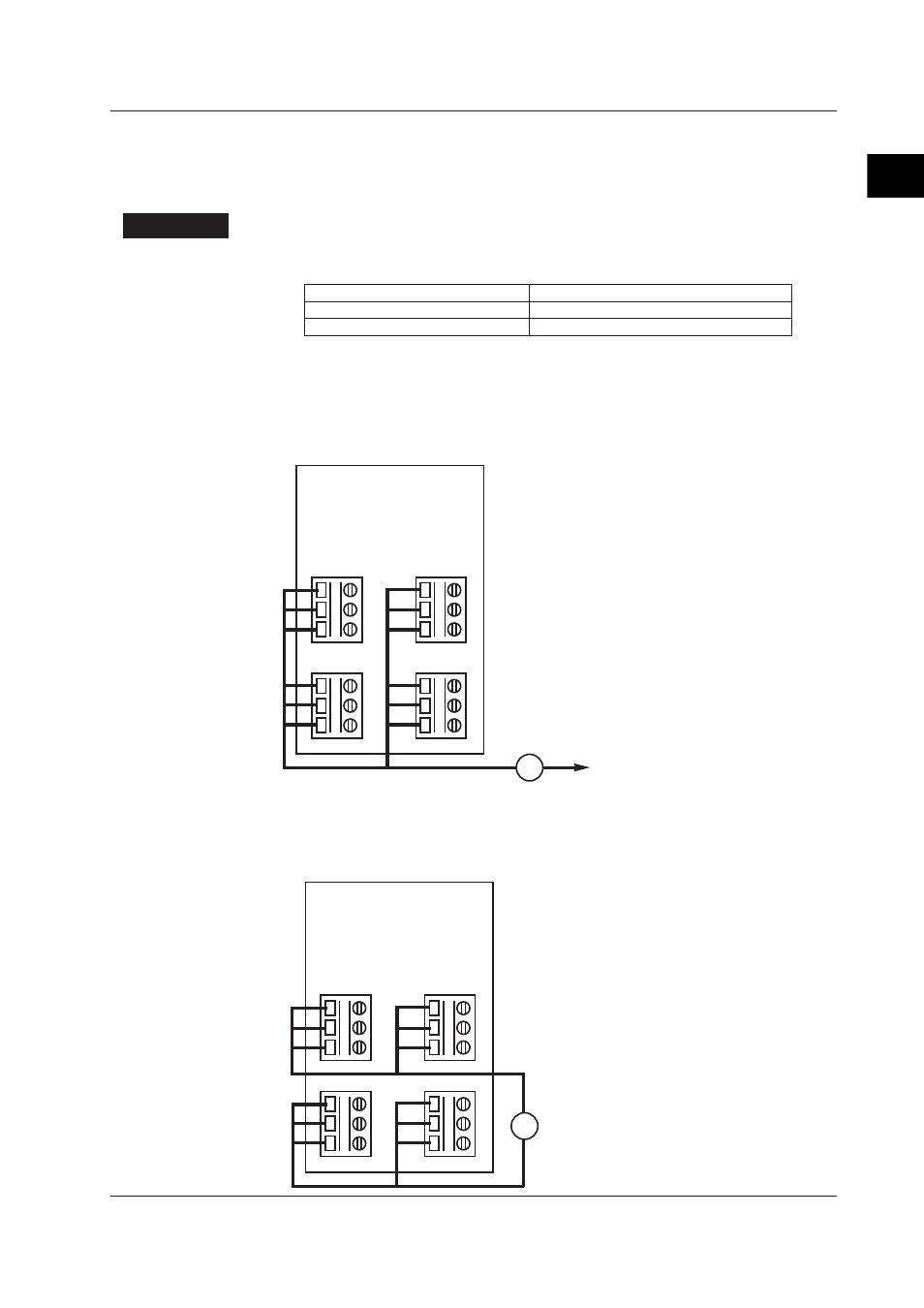
Measurement between Input Terminal and Earth Terminal
Short all terminals A, B, and b (1-3) on channels 1 through 4, then measure the
insulation resistance between the MX100/MW100’s or equivalent device’s functional
earth terminals. Be sure to attach the module and base plate when performing this
test.
A 1
B 2
b 3
3ch
A 1
B 2
b 3
1ch
A 1
B 2
b 3
4ch
A 1
B 2
b 3
2ch
M
M: Insulation resistance tester
To the functional earth terminal on
the MX100, MW100, or equivalent device
Measurement between Input Terminals
Measure the insulation resistance between a device whose terminals A, B, and b (1-3)
on channels 1 and 3 are all shorted and a device whose terminals A, B, and b (1-3) on
channels 2 and 4 are all shorted.
A 1
B 2
b 3
3ch
A 1
B 2
b 3
1ch
A 1
B 2
b 3
4ch
A 1
B 2
b 3
2ch
M
M: Insuration resistance tester
2.4 Tests of the 4-CH, High-Speed Universal Input Module (MX110-UNV-H04)