Yokogawa PC-Based MX100 User Manual
Page 64
2-35
SM MX100-01E
Testing
1
2
3
4
5
6
7
2.7.9
Dip Switch Operation Test (-B12, -B35 Only)
You can check whether the dip switches are operating normally by confirming that
measurements can be taken using the 1-gauge method.
(Confirmation using the 4-gauge method can be made with the measurement accuracy
and channel error tests. )
1.
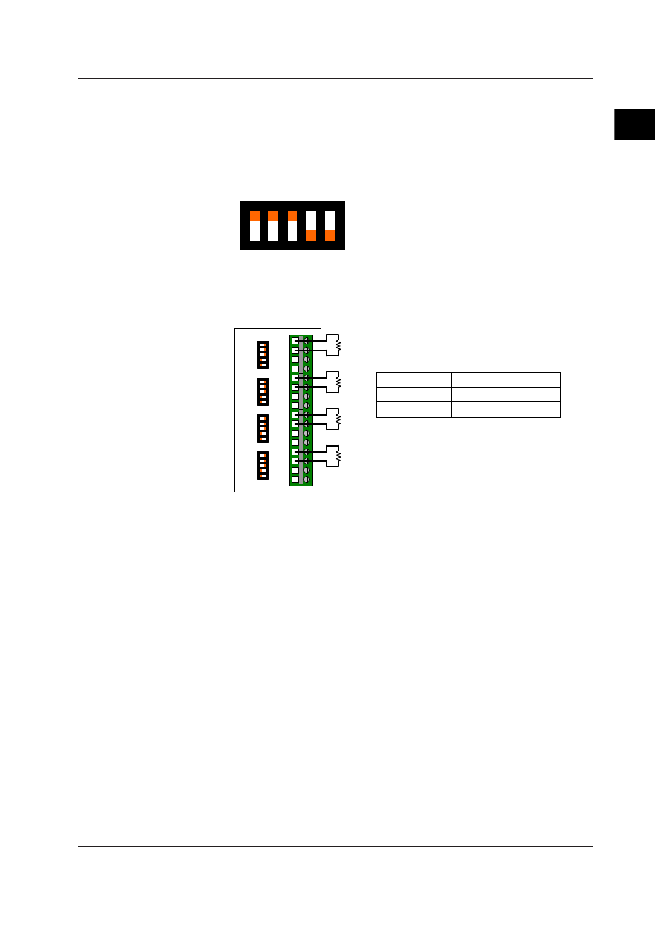
Set the dip switches for the 1-gauge, 2-wire method.
Dip switch settings
ON
1 2 3 4 5
SW1 to SW3: ON
SW4 to SW5: OFF
2.
Connect resistance independantly to all channels as shown in the figure below.
The wiring resistance of the module itself is large, and therefore needs to be
reduced as much as possible.
1
2
3
4
5
6
7
8
9
10
11
12
13
14
15
16
ON
1
2
3
4
5
ON
1
2
3
4
5
ON
1
2
3
4
5
ON
1
2
3
4
5
A/+V
B/ L
C/-V
D/ H
CH1
A/+V
B/ L
C/-V
D/ H
CH2
A/+V
B/ L
C/-V
D/ H
CH3
A/+V
B/ L
C/-V
D/ H
CH4
Resistance
Resistance
Resistance
Resistance
Test module
Resistance stated value
-B35
350Ω ± 0.01%
-B12
120Ω ± 0.01%
Resistance stated value
3.
Restore the initial balance values of all channels to the initial values from a PC via
communication.
4.
Enter the following settings.
Measured CH
All CH
Measurement range
2000 µSTR
Measurement interval
200 ms
Filters
OFF
Duration
10 s or more
5.
Confirm that the measured values are within the stated values.
Measured Value Stated Value
0
µ
STR ±400
µ
STR
2.7 Tests of the 4-CH Strain Input Module