Switches and keys, Connectors, User function keys – Yokogawa PC-Based MX100 User Manual
Page 17: Dip switch 1, Dip switch 2, Key lock function, Firmware update
1-10
SM MX100-01E
Switches and Keys
The MW100 has the following switches and keys. Some are included with options.
• Start and Stop keys
• User function key 1
• User function key 2
• Dip switch 1
• Dip switch 2
• Terminator switch (/C3 option)
• Power switch
User Function Keys
Actions set up using the Event/Action function can be executed by pressing the user
function keys on the front panel of the MW100.
The keys are assigned as follows by default.
Key
Display
Action
User function key 1
USER1
Write to setting values file
User function key 2
USER2
Load setting values file
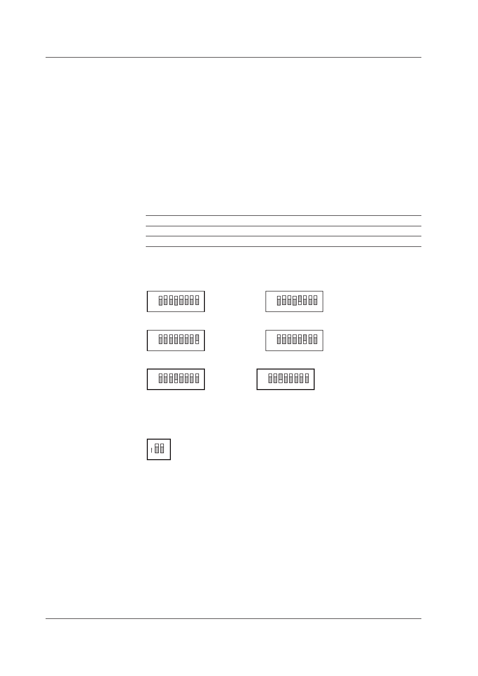
Dip Switch 1
Used to initialize the MW100 settings and for other functions.
• Normal operation
• Initialization of IP addresses and other settings
1
2
3
4
5
6
7
8
ON
1
2
3
4
5
6
7
8
ON
• Fixed IP address (192.168.0.10) • 10-Mbps half-duplex Ethernet communication
1
2
3
4
5
6
7
8
ON
1 2 3 4 5 6 7 8
ON
• Firmware update
1 2 3 4 5 6 7 8
ON
1 2 3 4 5 6 7 8
ON
Main unit
Web
Dip Switch 2
Turn all switches ON for normal operation. If the switches are set differently, the
instrument may not function correctly.
1
2
ON
Key Lock Function
You can apply a lock to the functions of the Start, Stop, and user function keys. The lock
prevents inadvertent execution of functions.
Connectors
The MW100 can come with the following connectors. The actually-installed connectors
depend on the power supply input section specifications and options.
• Ethernet
• RS-422A/485 connector (/C3 option)
• RS-232 connector (/C2 option)
• CF card slot
• Power supply inlet (power supply input section specification: -1M)
• Power supply screw terminals (power supply input section specification: -1W, -2M, -3W)
1.4 Functions of the MW100 Main Module