2 withstanding voltage test, 3 excessive input test, Procedure – Yokogawa PC-Based MX100 User Manual
Page 39
2-10
SM MX100-01E
2.4.2
Withstanding Voltage Test
For this test, the Four-Channel, High-Speed Universal Input Module is installed with the
MX100, MW100, or equivalent device. Perform this test after the test described in section
2.4.1, “Insulation Resistance Test.”
Procedure
Perform the withstanding voltage test on the same locations indicated for the
insulation resistance test (input terminal to earth, and between input terminals), then
confirm that the results meet the criteria below.
Be sure to attach the module and base plate when performing this test.
Measured Item
Criteria
Input terminal to earth terminal
AC3700 Vrms for 1 minute, with leakage of 2 mA or less
Between input terminals
AC2300 Vrms for 1 minute, with leakage of 1 mA or less
2.4.3
Excessive Input Test
Perform this test while in measurement mode.
Set the measurement interval to an arbitrary value greater than 50 ms.
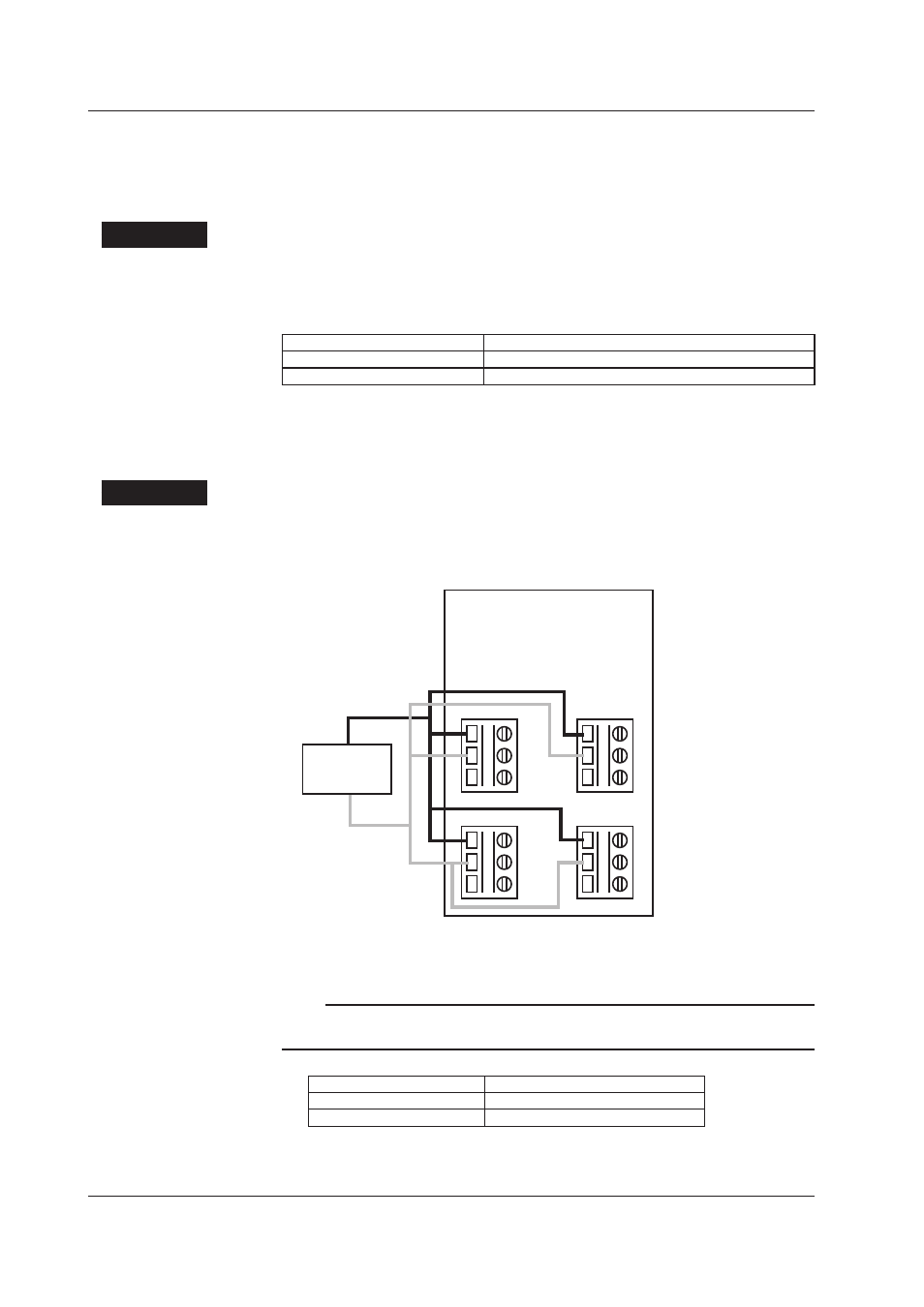
Procedure
Set the range for all channels to DC20 mV.
1.
Connect all A (1) and B (2) terminals separately on channels 1 through 4 as
shown in the figure below.
A 1
B 2
b 3
3ch
A 1
B 2
b 3
1ch
A 1
B 2
b 3
4ch
A 1
B 2
b 3
2ch
DC voltage
generator
2.
Apply the voltages below between the A and B terminals, and confirm that no
abnormalities occur.
Note
In the same manner as described in “Setting All Channels to Pt100/1 mA High Resolution
Range” below, connect terminals B and b (2, 3) then perform the excessive input test.
Applied Voltage
Duration
+20 V
10 seconds
-20 V
10 seconds
2.4 Tests of the 4-CH, High-Speed Universal Input Module (MX110-UNV-H04)