Procedure – Yokogawa PC-Based MX100 User Manual
Page 46
2-17
SM MX100-01E
Testing
1
2
3
4
5
6
7
2.5.5
Measurement Accuracy Test
Procedure
1.
Turn the power ON then OFF.
2.
Turn the power ON again, then allow the instrument to warm up for at least 10
minutes.
3.
Adjust so that the wires connected to the A, B, and b terminals have the same
resistance value.
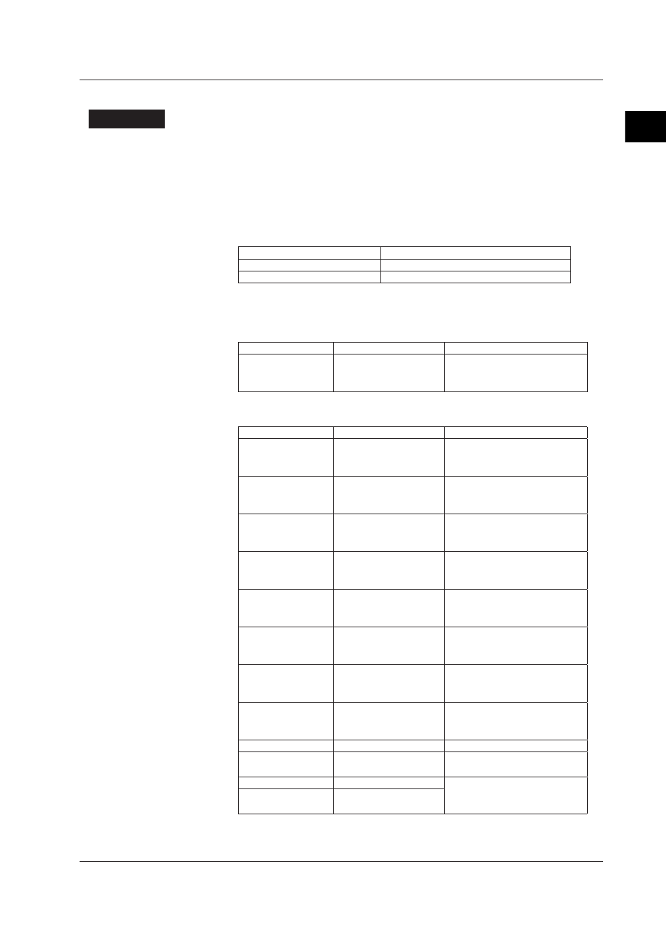
Set channel 2 as the measurement channel, and the measurement interval and
duration as follows:
Measurement Interval
Duration
100 ms
5 seconds or more
500 ms
10 seconds or more
4.
Confirm that the measured results are within the judgment criteria range in the
chart below.
100 ms Interval
Range
Input
Specifications
2 V
+2.0000 V
0.0000 V
-2.0000 V
±(0.1% of rdg. + 10 digits)
500 ms Interval
Range
Input
Specifications
20 mV
+2.0000 V
0.000 mV
-20.000 mV
±(0.05% of rdg. + 5 digits)
60 mV
+60.00 mV
0.00 mV
-60.00 V
±(0.05% of rdg + 2 digits)
200 mV
+200.00 mV
0.00 mV
-200.00 mV
±(0.05% of rdg + 2 digits)
2 V
+2.0000 V
0.0000 V
-2.0000 V
±(0.05% of rdg + 5 digits)
6 V
+6.000 V
0.000 V
-6.000 V
±(0.05% of rdg + 2 digits)
20 V
+20.000 V
0.000 V
-20.000 V
±(0.05% of rdg + 2 digits)
100 V
+100.00 V
0.00 V
-100.00 V
±(0.05% of rdg + 2 digits)
Pt100
18.52 Ω/-200.0°C
100.00 Ω/0.0°C
313.71 Ω/+600.0°C
±(0.05% of rdg + 0.3°C)
Cu10 GE
9.036 Ω/-0.0°C
±(0.1% of rdg + 2°C)
Pt100 High Resolution 100.00 Ω/0.00°C
157.33 Ω/150.00°C
±(0.05% of rdg + 0.3°C)
Cu10 GE
1.326 Ω/-200.0°C
±(0.1% of rdg + 2°C)
High Resolution
9.036 Ω/0.0°C
20.601 Ω/+300.0°C
2.5 Tests of the 10-CH, Medium-Speed Universal Input Module (MX110-UNV-H10)