Caution – Yokogawa PC-Based MX100 User Manual
Page 177
7-37
SM MX100-01E
Procedures for Disassembly
1
2
3
4
5
6
7
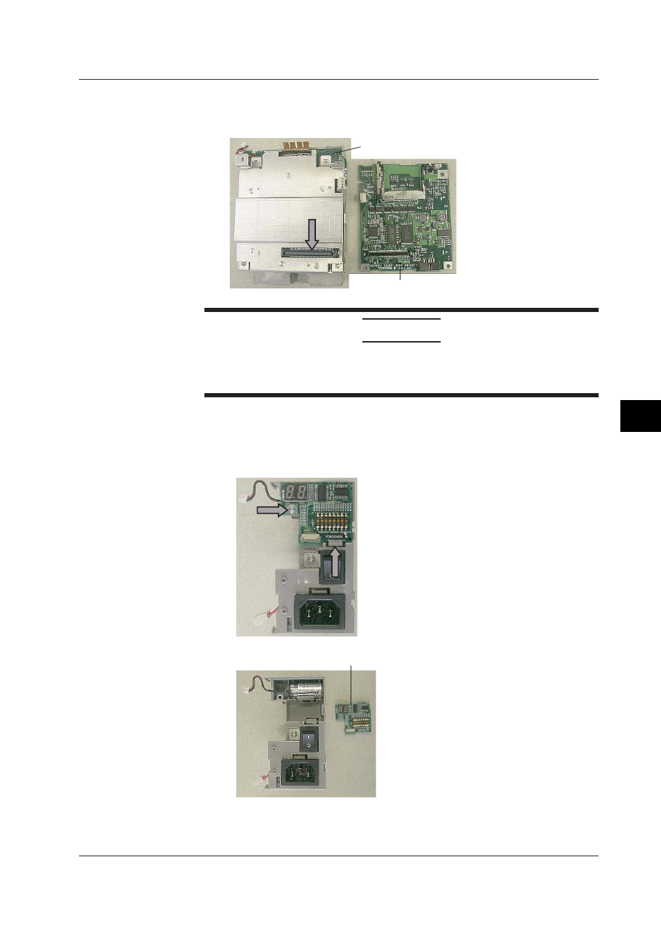
11.
The CPU Board and Memory Board are connected by the connector at the arrow
in the figure below.
Remove the CPU Board and Memory Board from the CPU Assembly.
Memory Board
CPU Board
CAUTION
The connector for the CPU Board and Memory Board are surface-mounted. If you
try to remove them forcibly, you might break off the soldering. Remove the boards
slowly and carefully.
Remove the Display Board and Battery Assembly
12.
Remove the screw indicated by the arrow in the top of the figure below.
13.
Push down the tab indicated by the lower arrow in the figure below, and pull out
the Display Board.
Unit with the Display Board removed
Display Board
14.
Remove the Battery Assembly.
7.9 Disassembling the MX100 Main Module