Yokogawa PC-Based MX100 User Manual
Page 56
2-27
SM MX100-01E
Testing
1
2
3
4
5
6
7
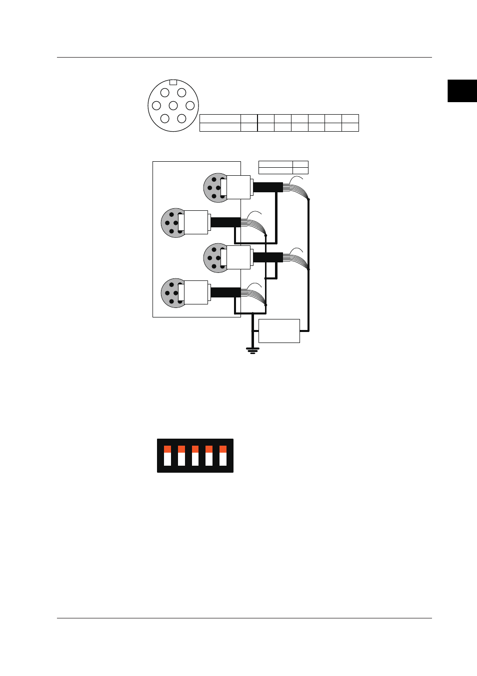
NDIS terminal pin and signal names
A
G
B
C
F
E
D
Pin name
Signal name
A
B
C
D
E
F
G
P
L
N
H COM PS NS
Diagram for wiring between NDIS input terminals
CH1
CH2
CH3
CH4
A1002JC
A1002JC
A1002JC
A1002JC
Pin name
Signal name
E
COM
Tester or
Withstanding
voltage
tester
• As the E terminal (COM) is common to all channels, it should be excluded when
performing the between-input terminal insulation resistance or withstanding voltage
tests. Also, the E terminals on all channels can be connected to each other.
• The cable shell, and the signal wires of channels 2 and 4 are grounded to all channels.
Dip switch settings
ON
1
2
3
4
5
SW1–SW5: ON
In order to ensure continuity from the MX100, MW100, or equivalent’s earth to the heat
sink of the module under test, you must fasten the module with screws after installing
onto the MX150 base plate.
2.7 Tests of the 4-CH Strain Input Module