Gas line connections, Installation – Teledyne 3060e - Ultra Trace oxygen analyzer User Manual
Page 45
Teledyne Electronic Technologies
Analytical Instruments
3-19
Installation
Installation
Installation
Installation
Installation
Ultra
Ultra
Ultra
Ultra
Ultra T
T
T
T
Trace Oxyg
race Oxyg
race Oxyg
race Oxyg
race Oxygen Anal
en Anal
en Anal
en Anal
en Analyz
yz
yz
yz
yzer
er
er
er
er
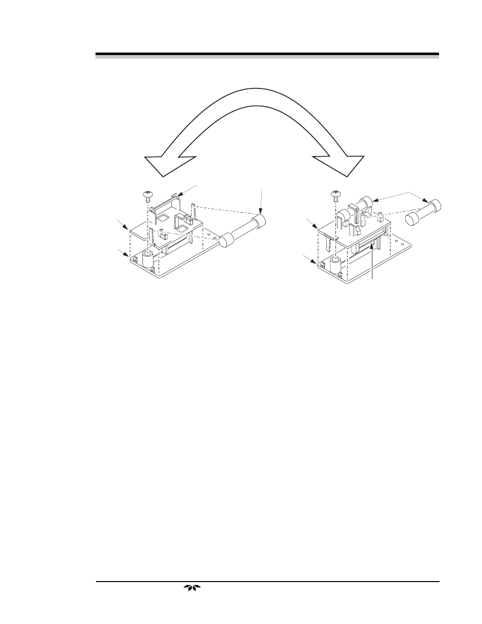
Jum per Bar
Cover
Fuse Block
North Am erican
Fuse
European 1.5 Am p Fuses
5 X 20 m m
Jum per Bar
Cover
Fuse Block
FL
IP
FU
SE BLOCK O
VE
R
Gas Line Connections
All of the gas lines to the system hook up at the back of the unit. See Figure 3-15.
All of the fittings are
1
/
4
" male VCR-type fittings, with the exception of the
compressed air inlet fitting. You have been provided with VCR glands, gaskets
and female nuts. The glands must be orbitally welded to electro-polished
1
/
4
"
tubing and then connected to the inlet/outlet connections on the instrument.
Use
3
/
4
" and
5
/
8
" wrenches to connect the gas lines. Insert the gasket
(P/N G284) between the fitting and tighten the female and male nuts until
finger-tight; then, by holding the male nut with the wrench, tighten the female
nut with the second wrench by 1/6 turn.
CAUTION:
Do not put any torque on the tubes welded on the sam-
pling system.
Check that each of the lines is hooked up to the correct connection. The lines
should be connected in the following order:
1. Span Gas In
If you choose to use a span gas to calibrate the analyzer, connect the
span gas tank to the span gas inlet.
Figure 3-14. Fuse Replacement