Teledyne 3060e - Ultra Trace oxygen analyzer User Manual
Page 43
Teledyne Electronic Technologies
Analytical Instruments
3-17
Installation
Installation
Installation
Installation
Installation
Ultra
Ultra
Ultra
Ultra
Ultra T
T
T
T
Trace Oxyg
race Oxyg
race Oxyg
race Oxyg
race Oxygen Anal
en Anal
en Anal
en Anal
en Analyz
yz
yz
yz
yzer
er
er
er
er
Voltage Selection and Fuse Changing
The voltage setting and fuses of the analyzer can be changed to international
standards. To change the voltage setting or fuses:
WARNING:
Disconnect all power from the analyzer before proceeding.
1. The AC power module is located on the back panel of the analyzer
(see Figure 3-15). Directly above the power cord receptacle is the
voltage select/fuse panel. To remove the cover, insert the tip of a
small blade screwdriver into the notch above the power cord recep-
tacle (see Figure 3-12) and carefully pry the cover loose.
2. Remove the cover and the fuse block assembly.
3. Pull the voltage selector card straight out of the housing by pulling
on the indicator pin (see Figure 3-12).
4. Turn the card so that the desired voltage can be read at the bottom.
5. Slide the indicator pin around the card so that it is at the top of the
card when the voltage is read at the bottom (see Figure 3-13).
6. Place the voltage selector card back into the housing. The edge
where the desired voltage is printed should go in first and the printed
side of the card should be facing down.
7. Replace the fuse block and the cover. Verify that the indicator pin is
pointing to the correct voltage.
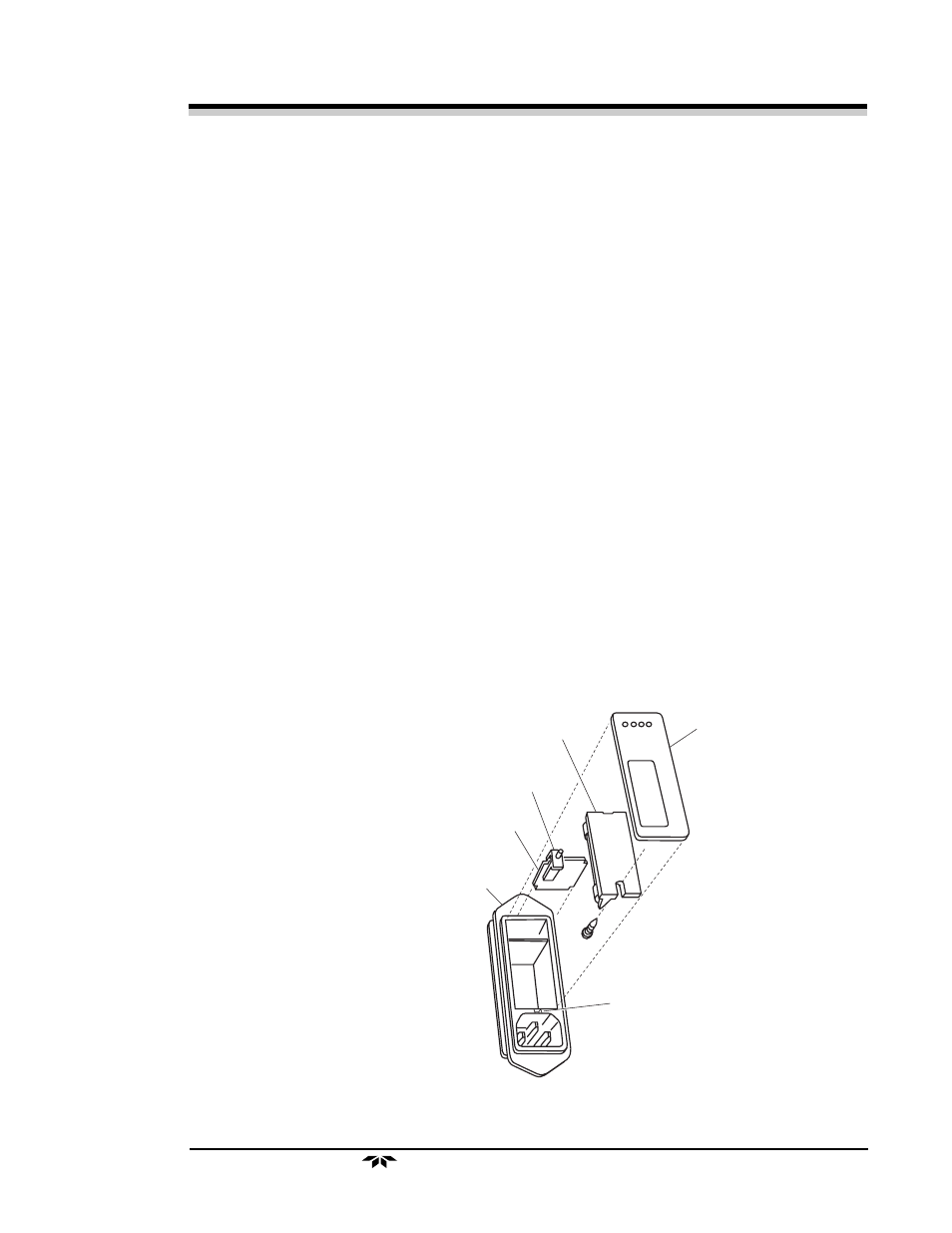
Housing
Voltage Selector Card
Indicator Pin
Fuse Block
Cover
Notch
Figure 3-12. Removing the Voltage Card