T2 ), System wiring page 7 - 27, I/o module (input module shown) – Franklin Fueling Systems Tank Sentinel (TS-1001, 2001, 504, 508 & 750) Installation User Manual
Page 70
SYSTEM WIRING
Page
7 - 27
7
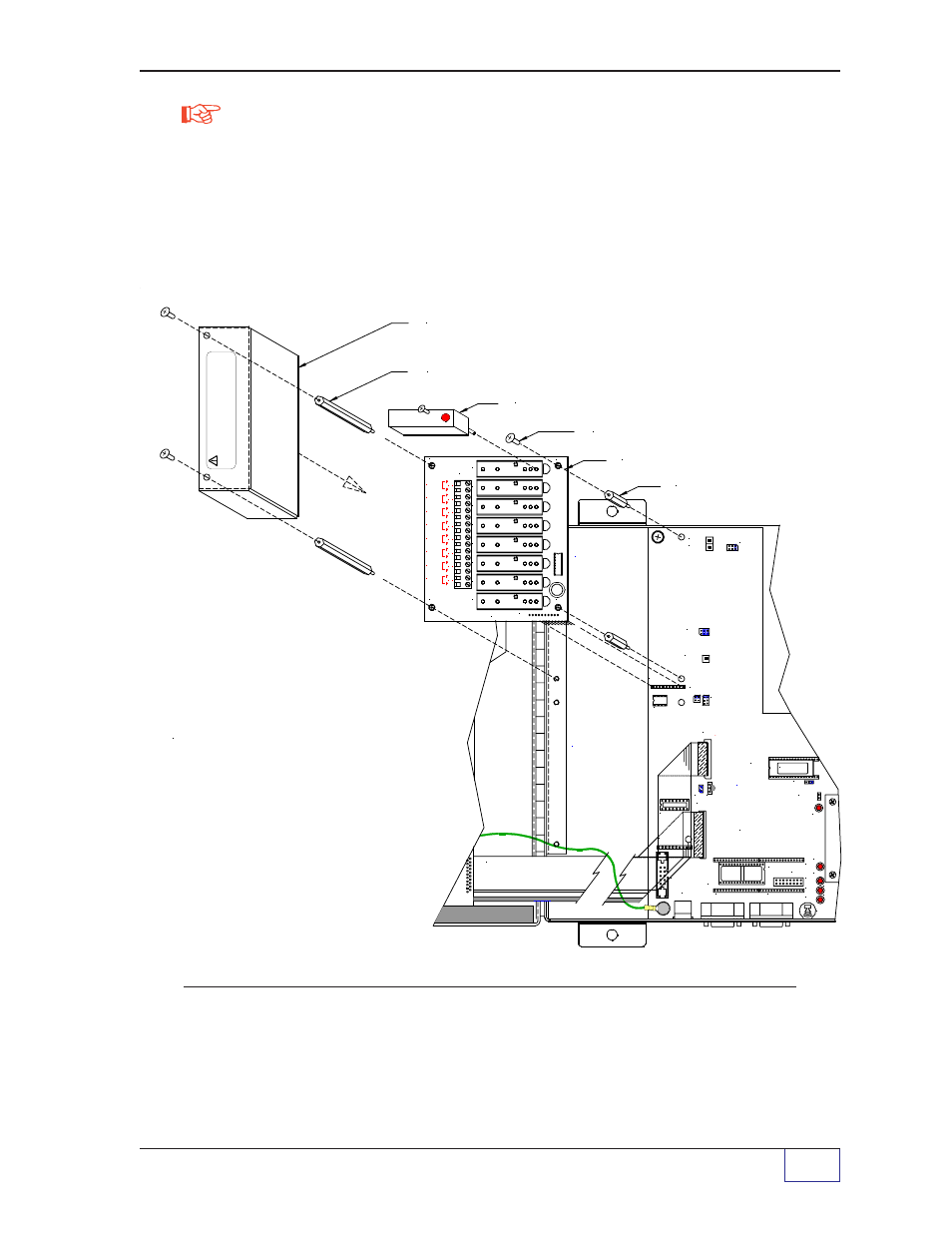
Order I/O (Input/Output) modules separately from the TS-IEM module. Output
modules are equivalent to either a single pole single throw, normally open
contact (FORM-A, SPST-NO Make ), or normally closed (FORM-B, SPST-NC,
Break ) contacts. Input modules exist in two versions: AC and DC.
See TABLE 7-5 (which follows the installation and wiring diagrams) for a listing
of available choices.
Figure 7-13b.
TS-IEM Internal Expansion Module Installation
NOTE
I/O MODULE (INPUT MODULE SHOWN)
S p a c e f o r
I n t e r n a l
E x p a n s i o n
I / O M o d u l e
# 1
S p a c e f o r
I n t e r n a l
E x p a n s i o n
I / O M o d u l e
# 2
J 1 D I S P L A Y & K E Y P A D
C A B L E T O J 6
NOTE:
The first TS-IEM Module
is installed at the upper left corner
of the TS-2001 console and plugs
into J12. This is the installation
location for consoles with one TS-IEM.
Field Installation Steps
1) Install the standoffs as shown
2) Use two #8-32 x 3/8 inch (9.5 mm) hold-down
screws at the right side, and the
two 3 inch (76.2 mm) standoffs at the right side
of the module,
3) Install wiring (see Wiring Diagram)
4) Install the Safety Shield with the
remaining two hold-down screws
The second TS-IEM Module is installed
at the lower left side of the console
and plugs into J10.
J 2
+
DC-
M T
I N / O U T 5
I N / O U T 6
I N / O U T 7
I N / O U T 8
+D
C
-
+D
C
-
AC
+D
C
-
+
DC-
AC
AC
AC
M T
I N / O U T 1
I N / O U T 2
I N / O U T 3
I N / O U T 4
AC
+D
C
-
+
DC-
+D
C
-
AC
AC
AC
M T
1 7 0 - 1 0 5 8
R L 7
R L 8
R L 6
R L 5
J 1
R L 4
R L 3
R L 2
R L 1
M T
CLEAR TERMINAL SAFETY-SHIELD
3 INCH (76.2 mm) STANDOFF (2)
M A I N
S Y S T E M
P C B d
J 2 2
U 5 0
J 5
U4
7
J 9
J 4
J 1 1
U 3 5
J 1 0
D T R
D 1 3
J 8
S 1
T X D
D 1 2
J 7
U 3 6
J 2 1
D C D
R X D
D 1 5
D 1 4
D 2
1 7 0 - 1 0 5 4
J 3
J 6
U 4 5
J 3 2
T P 3
J 1
J 1 2
U 1 0
J 2
TS-1001/N-N U10
VER No. DATE
TS-IEM Module PC Board
1 INCH (25.4 mm) STANDOFF (2)
T P 1
T P 2
J 3 3
# 8-32 x 3/8 INCH (9.5 mm) SCREW (4)
W
ARNING:
LETHAL
V
O
L
TAGES COULD EXIST !
LOCA
T
E
AND
DISCONNECT ALL
EXTERNAL
POWER SOURCES
BEFORE WORKING ON OR SER
VICING THESE CIRCUITS —
REINST
ALL THIS COVER BEFORE OPERA
TING EQUIPMENT
.
(
T2
)