Liquid level probe - wiring detail, Ts-db1 splice kit (epoxy filled) – Franklin Fueling Systems Tank Sentinel (TS-1001, 2001, 504, 508 & 750) Installation User Manual
Page 52
SYSTEM WIRING
Page
7 - 9
7
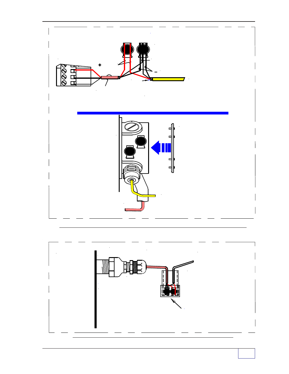
Figure 7-4a.
Console to Liquid Level Probe Wiring Detail (with J-Box)
Figure 7-4b.
Console to Liquid Level Probe Detail (without J-Box)
Liquid Level Probe - Wiring Detail
3 WIRE CABLE FROM CONSOLE
TO SPLICE:
INSERT UNSTRIPPED WIRES & USE SLIP-JOINT
PLIERS TO SEAT BLACK PIECE
A 3/4 to 1/2 NPT
bushing is required
for the compression
gland / cord grip
fitting when a
3/4 NPT Junction Box
is used
CABLE FROM CONSOLE
EYS FITTING (epoxy filled
seal fitting) is not shown
P
R
O
BE N
-(BLK)
SHLD
Probe N - Tank N
P
+(RED)
WHT
(RED)
or YEL
SEE WIRING ABOVE
WEATHERPROOF
JUNCTION BOX
COVER & GASKET
IS INSTALLED AFTER
PROBE IS TESTED
CABLE TO PROBE
3 or 4 WIRE CABLE
TO PROBE
(the white wire
may be cut off)
3 POSITION,
NO-STRIP ELECTRICAL CONNECTORS
(BLK)
SHLD
Also see Chapter 5 about Weatherproof Junction Boxes
CABLE
FROM
CONSOLE **
A 3/4 to 1/2
NPT reducing
coupling and a
compression
gland / cord-
grip fitting
is required
when a
3/4 NPT
Junction Box
is not used
COMPRESSION
FITTING
(SUPPLIED)
NOTE
** = COIL A
SERVICE-LOOP OF BOTH
CABLES TOGETHER AND
TIE TO THE RMC
SEAL ALL FITTING THREADS
WITH UL APPROVED &
CLASSIFIED "PIPE DOPE"
REDUCING
COUPLING
RMC
Some sensors, which are
suspended above a surface,
may still require the use
of a weatherproof junction
box
TS-DB1 SPLICE KIT
(EPOXY FILLED)
CABLE FROM
PROBE **
(OR SENSOR)