Franklin Fueling Systems Tank Sentinel (TS-1001, 2001, 504, 508 & 750) Installation User Manual
Page 41
LEVEL PROBE INSTALLATION
Page
6 - 7
6
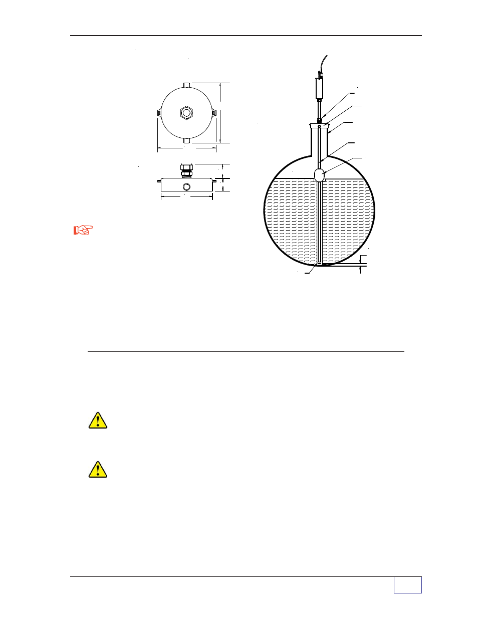
Figure 6-2
TSP-LL2C Chemical Probe Installation with a 2" (50.8 mm) TSP-SSP
Float
Floats – Standard Cautions and Notes
CAUTION Using the wrong floats on the TSP-LL2 level probe shaft will result
in erratic operation and incorrect level and volume data. Only use floats that are
designed for use with the TSP-LL2 liquid level probe.
CAUTION Avoid possible float damage, slide both floats down so they are at
the bottom of the probe shaft before you install the probe into the tank.
Other “2 inch” floats (model numbers TSP-IGF2, TSP-IDF2, and TSP-SSP) may be
used with the TSP-LL2 liquid level probe in special applications/products. Follow
the installation instructions provided with these floats.
NOTE: STEEL
TANKS MAY
REQUIRE AN
ISOLATION
BUSHING
PER LOCAL
CODES
SWAGELOCK
(MOUNTED)
5.0"
(127 mm)
1.25" (31.8 mm)
1.50" (38.1 mm)
FLOAT RETAINER
P R O D U C T
A I R
5.75"
(146 mm)
6.58" (167.1 mm)
TSP-K4AS
STAINLESS STEEL RISER CAP ADAPTER
FOR 4-INCH (101.6 mm) DIA. THREADED
RISER PIPES (8-NPT SS)
TSP-SSP PRODUCT FLOAT
(STAINLESS STEEL)
INSTALL PROBE
1/4" (6.4 mm) ABOVE
BOTTOM OF TANK
SWAGELOCK FITTING
(STAINLESS STEEL)
TSP-K4AS STAINLESS STEEL
RISER CAP ADAPTER
4 INCH DIA. SS RISER PIPE
(ANSI SCH. 40, MM 8-NPT)
DN115 BSP 4-11
TSP-LL2C PROBE SHAFT
(STAINLESS STEEL)
NOTE
1) Seal fitting threads with
pipe dope that is compatible
with the chemicals stored in the tank.
2.) With the probe resting on the bottom
of the tank, hand-tighten the top swagelock
fitting and mark the top of the swagelock fitting
with an indelible ink pen.
3.) Pull up on the probe 1/4" (6.4 mm) and tighten
the upper fitting so the probe doesn't move.