Franklin Fueling Systems T5 Retrofit LCD Display Installation User Manual
T5 retrofit lcd display, Installation instructions
©2007 FFS 000-0526 Rev. B
T5 Retrofit LCD Display
Installation Instructions
Tools Required
•
#1 Phillips screwdriver
•
X-acto knife (or equivalent)
•
3/16 Nut driver
Replacing an Existing LCD Display, TS-5 and TS550/5000
1. Power down the system.
2. Open the system door.
3. TS550/5000 models only, remove the shield installed
on the back of the door.
4. Remove the old LCD Display. Carefully disconnect
cables at J2, J3 and J4.
5. Slide the wide ribbon cable through the ferrite bead that
is already installed, and connect to J2.
6. T5 Only - Fold the wide ribbon cable over as shown in
Figure 1.
7. Fit the LCD Display into the opening from the door-
back and secure using the four 3/16 inch standoffs
(T550/5000) or #4-40 screws (T5).
8. Locate J3 (Figure 1) and gently pull the tab open by
grasping the sides and pulling away slightly. Insert the
narrow ribbon cable into J3: The side with the metal
fingers should face you and the backing face away from
you. Once the cable is properly seated gently push the
tab back in to secure the cable.
9. Plug the 2 wire cable into J4 (Figure 1) so that the
center key is facing away from you.
10. T550/5000 Only - Replace the metal shield; making
sure that the ground wire is captured by one of the
mounting screws.
Adding an LCD Display to the TS-550/5000
1. Power down the system.
2. Open the system door.
3. Remove the shield installed on the back of the door.
4. Remove the four screws and standoffs that secure the
LCD Display blank-off plate to the back of the door.
5. Remove the LCD Display blank-off plate (the blank-off
plate may stick to the overlay; gently pry it off).
6. From the inside of the enclosure, use a sharp pointed
knife to cut a small “X” in the overlay at the four corners
of the LCD Display enclosure opening in the metal door.
7. Use a sharp knife to remove the portion of the overlay
covering the LCD Display opening.
8. Fit the LCD Display into the opening from the door-
back and secure using the four 3/16 inch standoffs with
lock-washers.
9. Slide the wide ribbon cable through the ferrite bead
(Figure 1) so that the side of the cable with the metal
fingers is facing the same direction as the double
sided tape on the ferrite bead. Position the ferrite bead
approximately 1 inch from the right-hand corner of the
circuit board. This will allow future printer installation.
10. Plug the wide ribbon cable into plug J2 (see Figure 1)
on the interface PCB so that the side with the backing is
facing you and the side with the metal fingers is away.
11. Remove the tab from the back of the ferrite bead to
expose the adhesive and push firmly onto the back of
the door as shown in Figure 1.
12. Locate J3 (Figure 1) and gently pull the white tab open
by grasping the sides and pulling away slightly. Insert
the narrow ribbon cable into J3: The side with the metal
fingers should face you and the backing face away
from you.Once the cable is properly seated, gently
push the tab back in to secure the cable.
13. Plug the 2 wire cable into J4 (Figure 1) so that the
center key is facing away from you.
14. Replace the metal shield; making sure that the ground
wire is captured by one of the mounting screws.
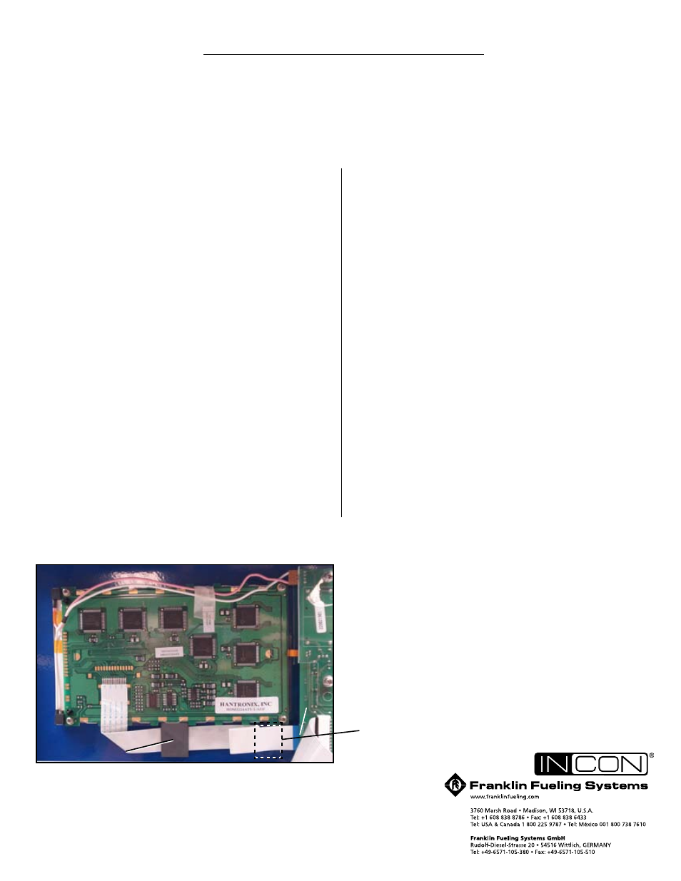
Figure 1. T5 Board Installation (TS-5 shown)
J2
J4
J3
Ferrite bead
Ferrite bead location for TS-550/5000