Figure 7-6. alarm-relay output wiring, Page 7 - 12 tank sentinel, Installation guide – Franklin Fueling Systems Tank Sentinel (TS-1001, 2001, 504, 508 & 750) Installation User Manual
Page 55: Alarm relay output wiring & schematic, Enlarged view of terminal strip # j16 & j15
7
Page
7 - 12
TANK SENTINEL
®
INSTALLATION GUIDE
W
ARNING:
LETHAL
VOL
TAGES COULD EXIST !
LOCA
T
E
AND
DISCONNECT ALL
EXTERNAL
POWER
SOURCES
BEFORE WORKING ON OR SER
VICING THESE CIRCUITS —
REINST
ALL THIS COVER BEFORE OPERA
TING EQUIPMENT
.
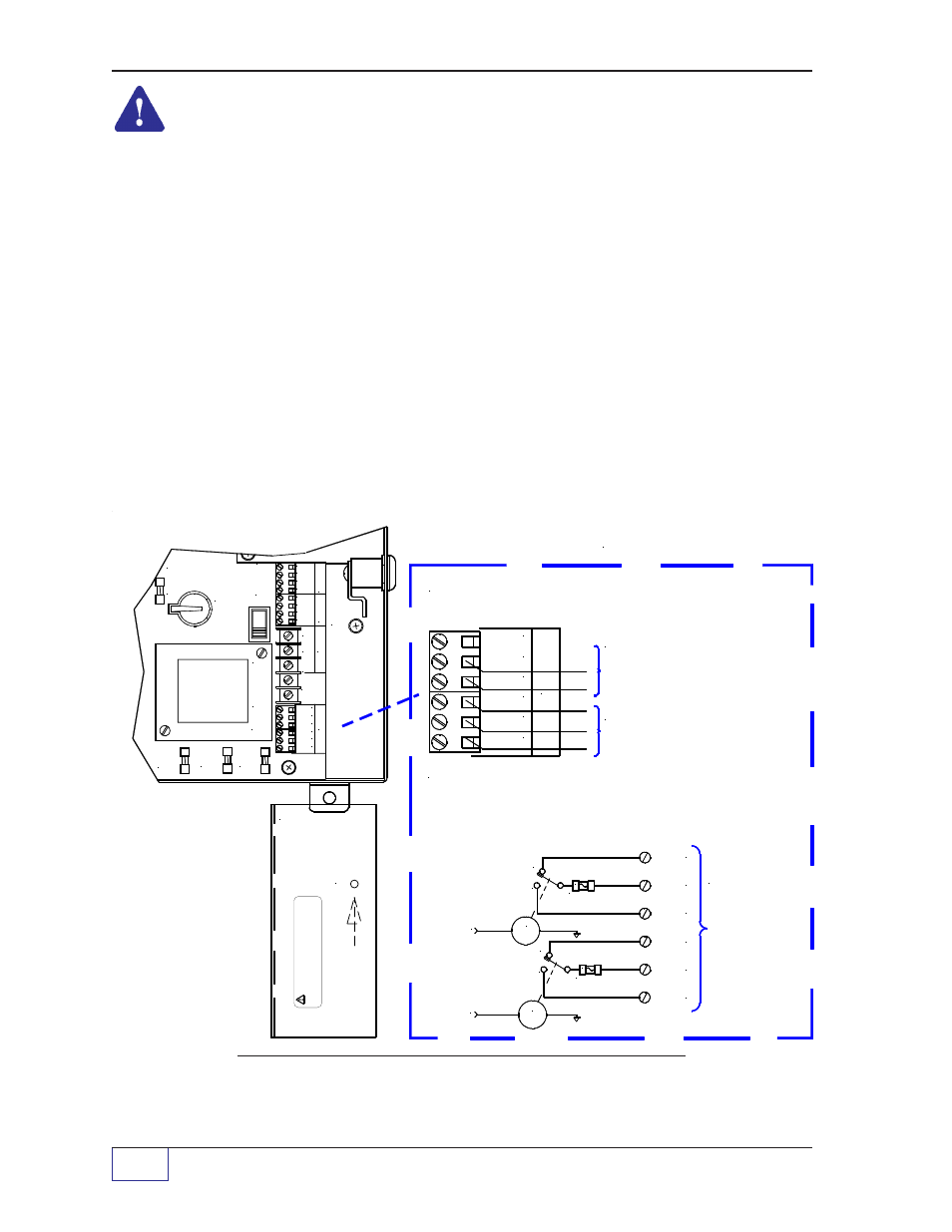
WARNING
Avoid electrical shock hazards. External power sources may be
present — locate and disconnect all external power sources before wiring or
servicing these circuits.
The alarm-relay interface terminals are located at J16 and J15, below the
console line power terminal strip. The interface terminals for each relay includes
a fused common (C) contact, a normally open (NO) contact, and normally
closed (NC) contact. You may choose whether you want the alarm circuit to be
normally open (closes/makes upon alarm) or normally closed (opens/breaks
upon alarm). See Figure 7-6 for this circuit.
Wire and Contact Ratings
Alarm circuits should be wired with a minimum of 18 AWG (1.0 mm) wire, type
TFFN, THWN, or THHN. Alarm relay contacts are rated for 3 amps at 125/250
VAC or 30 VDC. Do not exceed these maximum ratings.
Figure 7-6.
Alarm-Relay Output Wiring
P O W E R
T E R M I N A L
S A F E T Y S H I E L D
( C L E A R C O V E R )
NC 1
ALARM
SIGNAL 2
FROM CPU
d d
ALARM
SIGNAL 1
FROM CPU
NC 2
C 2
NO 2
C 1
NO 1
TANK SENTINEL
"PROGRAMMABLE"
ALARM-RELAY
OUTPUTS
CONTACT
RATINGS:
3 AMPS MAX.
@ 30 VDC
125/250 VAC
Remote/External
Alarm Outputs
R
E
LA
Y
O
U
TP
U
T
S
F 1 6
F 1 7
F 1 5
N O 2
C 2
RE
L
A
Y
O
U
T
PU
T
S
N O 2
N.C.
F15
2AG, 3A
N.O.
C
N.C.
N.O.
C
F16
2AG, 3A
AL
RLY 1
AL
RLY 2
WARNING: AVOID ELECTRICAL SHOCK HAZARDS.
EXTERNAL POWER SOUCES MAY BE PRESENT -
LOCATE AND DISCONNECT ALL EXTERNAL POWER SOURCES
BEFORE WIRING OR SERVICING THESE CIRCUITS.
Alarm Relay Output Wiring & Schematic
Enlarged View of Terminal Strip # J16 & J15
P O W E R
O N
S W 1
O F F
SA
F
E
T
Y
GN
D
J 1 5
N O 1
N C 2
J 1 6
C 1
N C 1
GN
D
PO
W
E
R
J 1 7
L1
NE
U
T
N O 1
C 2
N C 2
C 1
N C 1
TS
-
L
L
D
IN
P
U
T
S
G N D
+
+
G N D
I N 2
d d
J 1 4
B 1
D S Y
S . R T N
I N 1
J 1 3
F 1 4
4 8 5 B
4 8 5 A
Suggested Use - Optional:
INCON TS-RA1 (or TS-RA2) & TS-RK
Remote Tank Overfill Alarm Outputs.
See these manuals for further details.