Encoder counter control register 0 – Samsung S3F401F User Manual
Page 53
S3F401F_UM_REV1.00
ENCODER COUNTER
4-5
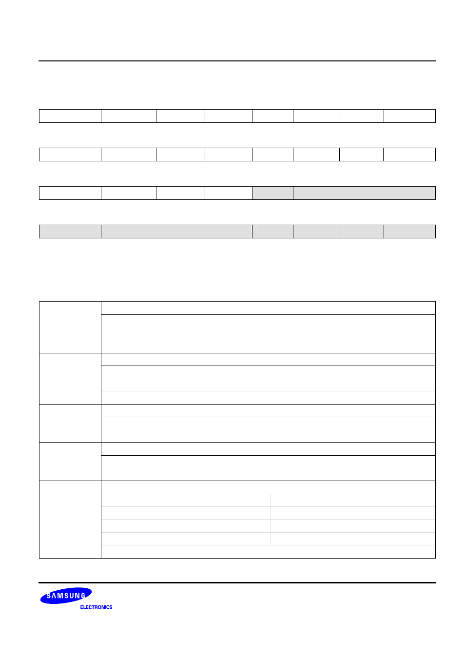
Encoder Counter Control Register 0
ENCCON0 (0x000)
Access: Read/Write
31 30
29
28
27
26
25
24
−
−
−
−
−
−
−
−
R/W-0 R/W-0
R/W-0
R/W-0
R/W-0 R/W-0 R/W-0 R/W-0
23 22
21
20
19
18
17
16
−
−
−
−
−
−
−
−
R/W-0 R/W-0
R/W-0
R/W-0
R/W-0 R/W-0 R/W-0 R/W-0
15 14
13
12
11
10
9
8
−
−
−
−
DBGEN
ENCCLKSEL[10:8]
R/W-0 R/W-0
R/W-0
R/W-0
R/W-0 R/W-0 R/W-0 R/W-0
7 6
5
4
3
2
1
0
PZCLEN
ENCFILTER[6:4]
ESELZ
ENCEN
SCNTCL
PCNTCL
R/W-0 R/W-0
R/W-0
R/W-0
R/W-0 R/W-0 R/W-0 R/W-0
W: Write
R: Read
-0: 0 After reset
-1: 1 After reset
-U: Undefined after reset
PCNTCL
Position Counter (PCNT) Clear Bit
0 = No effect
1 = Clear the counter register
Note: This bit is auto-clear bit.
SCNTCL
Speed Counter (SCNT) Clear Bit
0 = No effect
1 = Clear the counter register
Note: This bit is auto-clear bit.
ENCEN
Encoder Counter Block Enable Bit
0 = Disable encoder counter block
1 = Enable encoder counter block
ESELZ
Phase Z Edge Type Selection Field
0 = Falling edge is selected for PHASEZ
1 = Rising edge is selected for PHASEZ
ENCFILTER
Filter Clock Selection Field of Encoder Counter
000 = ENCCLK
100 = ENCCLK /16
001 = ENCCLK /2
101 = ENCCLK /32
010 = ENCCLK /4
110 = ENCCLK /64
011 = ENCCLK /8
111 = ENCCLK /128
Note: Only 5 times same level in a row is recognized as effective signal.