Inverter motor control register 0 – Samsung S3F401F User Manual
Page 105
INVERTER MOTOR CONTROLLER (IMC)
S3F401F_UM_REV1.00
6-26
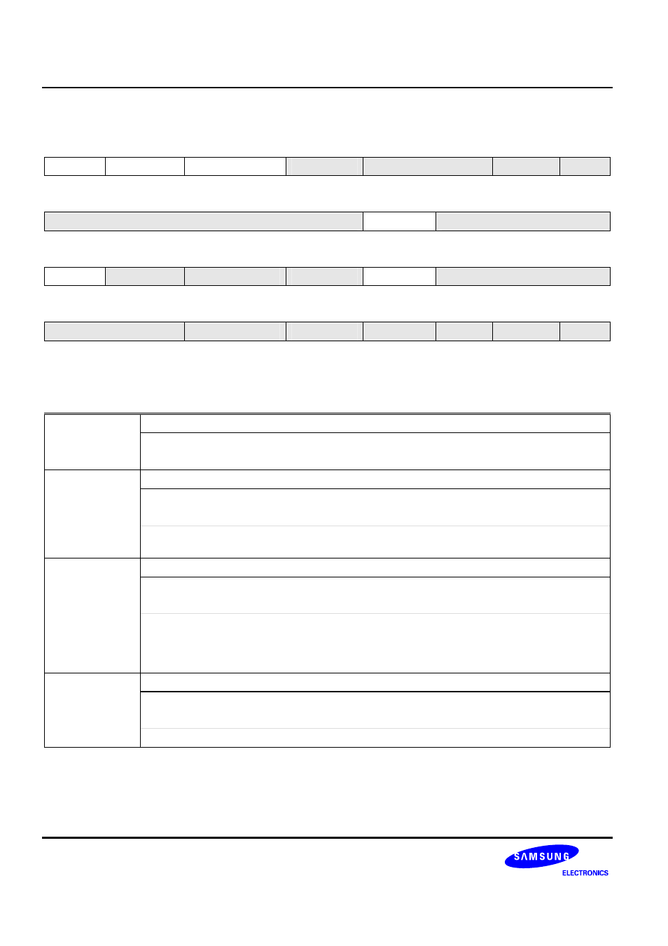
Inverter Motor Control Register 0
IMCON0 (0x000)
Access: Read/Write
31 30
29
28 27
26
25
24
–
–
–
DBGEN
SYNCSEL[27:26]
P25
R/W-0 R/W-0
R/W-0
R/W-0 R/W-0 R/W-0 R/W-0
R/W-0
23 22
21
20 19
18
17
16
NUMSKIP[23:21]
–
IMCLKSEL[18:16]
R/W-0 R/W-0
R/W-0
R/W-0 R/W-0 R/W-0 R/W-0
R/W-0
15 14
13
12
11 10 9 8
–
PWMOUTEN
PWMOUTOFFEN
PWMOFFEN
–
IMFILTER [10:8]
R/W-0 R/W-0
R/W-0
R/W-0 R/W-0 R/W-0 R/W-0
R/W-0
7 6
5
4 3
2
1
0
ESELPWMOFF6[7:6]
PWMPOLD
PWMPOLU
PWMSWAP
WMODE
IMMODE
IMEN
R/W-0 R/W-0
R/W-0
R/W-0 R/W-0 R/W-0 R/W-0
R/W-0
W: Write
R: Read
-0: 0 After reset
-1: 1 After reset
-U: Undefined after reset
IMEN
Inverter Motor Block Enable/Disable Control Bit
0 = Disable IMC Block
Æ IMCNT is cleared to 0 automatically
1 = Enable IMC Block
IMMODE
Inverter Motor Mode Selection Bit
0 = Tri-angular shape
1 = Saw-tooth shape
This bit can
be changed
only when
IMCON.0
is
0
.
If this bit is set to ‘1’, comparison with ‘0’ is no effect (INT_ZEROx will not be occurred.)
WMODE
Write Mode Selection of Compare Register
0 = Immediate write
1 = Synchronous write
Note: In the synchronous write, if IMCNT equals to 0 or TOPCMP, compare registers including
dead-time compare register which are written are updated simultaneously. Synchronous write is related
to NUMSKIP. For example, if NUMSKIP is 30, synchronous write happens only one time in every 30
times. ADC trigger signal is the same situation.
PWMSWAP
Swapping of PWMxUx and PWMxDx
0 = No Swap
1 = Swap
Note: This bit can be changed only when IMCON.0 is 0.