Control register 1 – Samsung S3F401F User Manual
Page 217
SSP
S3F401F_UM_REV1.00
10-16
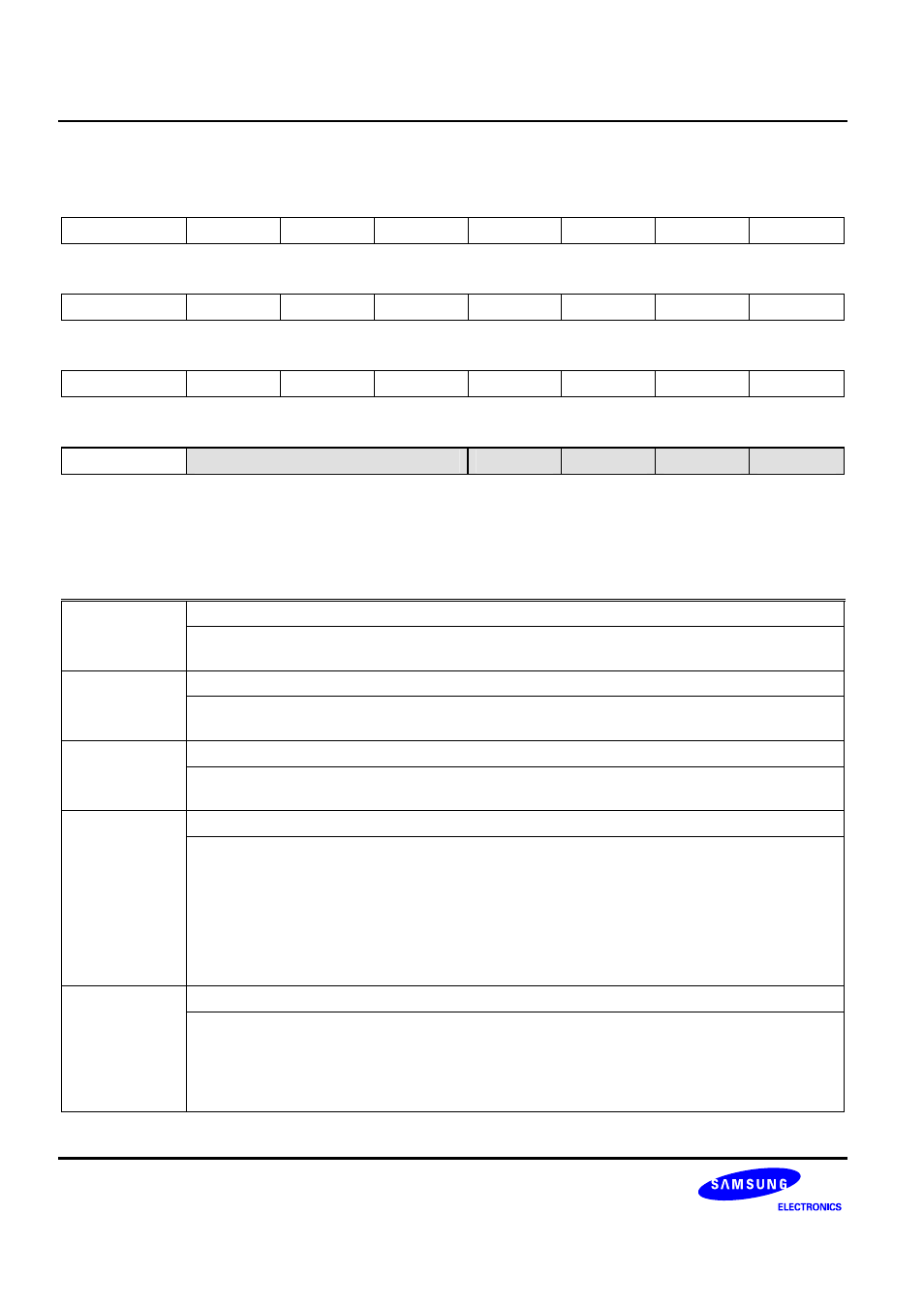
Control Register 1
SSPCR1 (0x004)
Access: Read/Write
31
30 29 28 27 26 25 24
−
−
−
−
−
−
−
−
R/W-0 R/W-0
R/W-0
R/W-0
R/W-0 R/W-0 R/W-0 R/W-0
23
22 21 20 19 18 17 16
−
−
−
−
−
−
−
−
R/W-0 R/W-0
R/W-0
R/W-0
R/W-0 R/W-0 R/W-0 R/W-0
15
14 13 12 11 10 9 8
−
−
−
−
−
−
−
−
R/W-0 R/W-0
R/W-0
R/W-0
R/W-0 R/W-0 R/W-0 R/W-0
7
6 5 4 3 2 1 0
−
RXIFLSEL[6:4]
SOD
MS
SSE
LBM
R/W-0 R/W-0
R/W-0
R/W-1
R/W-0 R/W-0 R/W-0 R/W-0
W: Write
R: Read
-0: 0 After reset
-1: 1 After reset
-U: Undefined after reset
LBM Loop-Back
Mode
Bit
0 = Normal serial port operation enabled
1 = Output of transmit serial shifter is connected to input of receive serial shifter internally.
SSE
Synchronous Serial Port Enable Bit
0 = SSP operation disabled
1 = SSP operation enabled
MS
Master or Slave Mode Selection Bit
0 : Device configured as master
1 : Device configured as slave
SOD
Slave-mode Output Disable Bit
This bit is relevant
only in the slave mode(MS=1). In multiple-slave systems, it is possible for a
PrimeCell SSP master to broadcast a message to all slaves in the system while ensuring that
only one slave drives data onto its serial output line. In such systems the RXD lines from
multiple slaves could be tied together. To operate in such systems, the SOD bit can be set if the
PrimeCell SSP slave is not supposed to drive the SSPTXD line.
0 = SSP can drive the SSPTXD output in slave mode.
1 = SSP must not drive the SSPTXD output in slave mode.
RXIFLSEL
Receive Interrupt FIFO Level Selection Field
001 = Trigger points
Receive FIFO becomes >= 1/8 (byte)
010 = Trigger points
Receive FIFO becomes >= 1/4 (half word)
100 = Trigger points
Receive FIFO becomes >= 1/2 (word)
Others = Reserved