Samsung S3F401F User Manual
Page 106
S3F401F_UM_REV1.00
INVERTER MOTOR CONTROLLER (IMC)
6-27
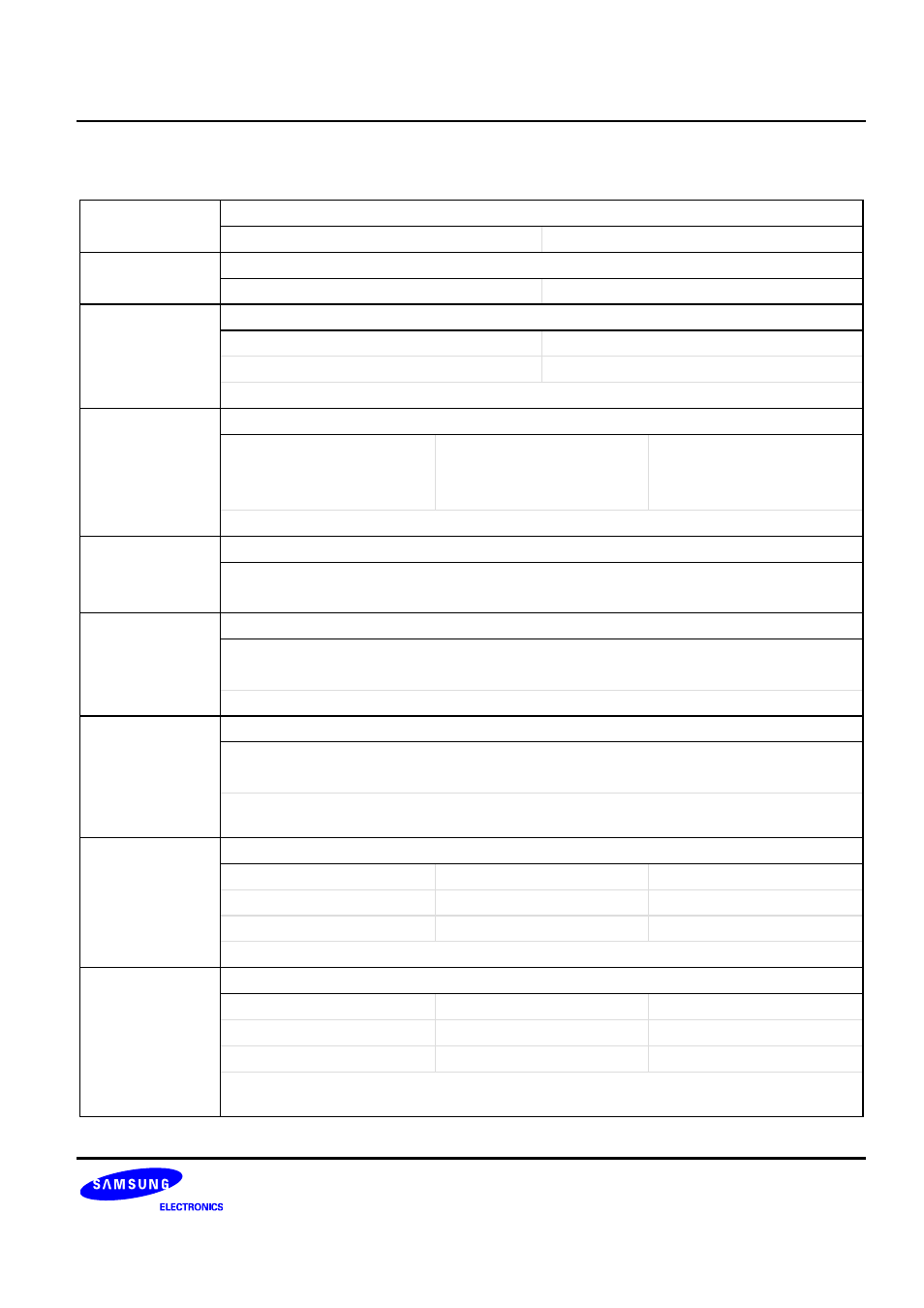
Inverter Motor Control Register 0 (Continued)
IMCON0 (0x000)
Access: Read/Write
PWMPOLU
PWMxU0/1/ 2 ‘s Polarity Selection Bit
0 = Low start
1 = High start
PWMPOLD
PWMxD0/1/2’s Polarity Selection Bit
0 = Low start
1 = High start
ESELPWMOFF
PWMxOFF Active Type Selection Field
00 = Falling edge
10 = Low level
01 = Rising edge
11 = High level
Note: These bits must be changed only when IMCON.0 is 0.
IMFILTER
Filter Clock Selection of PWMxOFF pin
000 = PCLK
011 = PCLK /8
110 = PCLK /64
001 = PCLK /2
100 = PCLK /16
111 = PCLK /128
010 = PCLK /4
101 = PCLK /32
Note: Only 6 times same level in a row is recognized as effective signal.
PWMOFFEN
PWMxOFF Enable Bit
0 = Disable Fault Detection of PWMxOFF
1 = Enable Fault Detection of PWMxOFF
PWMOUTOFFEN PWM Output Disable by PWMxOFF
0 = Disable PWM Output Disable by PWMxOFF
1 = Enable PWM Output Disable by PWMxOFF
Note: If this bit is set to ‘1’ and PWMxOFF condition is met, the PWM output goes to High-Z state.
PWMOUTEN
PWM Output Enable Bit
0 = Enable PWM output signal
1 = Disable PWM output signal
The PWM output goes to High-Z state if this bit is set to 1. This bit can be used in the
debugging time.
IMCLKSEL
Inverter Clock (IMCLK) Selection Field
000 = PCLK
011 = PCLK /8
110 = PCLK /64
001 = PCLK /2
100 = PCLK /16
111 = PCLK /128
010 = PCLK /4
101 = PCLK /32
Note: The clock source of dead-time compare register is IMCLK.
NUMSKIP
Numbers of Skip for Motor Match Interrupt Field
00000 : No skip
00011 : 3 times skip
11101 : 29 times skip
00001 : 1 time skip
….
11110 : 30 times skip
00010 : 2 times skip
11100 : 28 times skip
11111 : 31 times skip
This field can determine the number of skip for motor match interrupt and ADC trigger signal.
The unit of skip is PWM full cycle.