Samsung S3F401F User Manual
Page 156
S3F401F_UM_REV1.00
I/O
PORTS
8-7
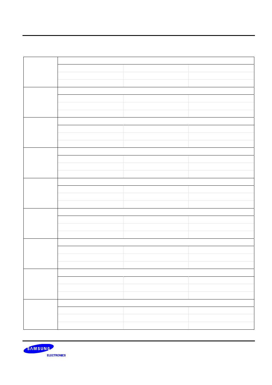
PORT0 Control Register (Continued)
PCON0L (0x004)
Access: Read/Write
P0.5 PORT
0.5
00 = Input Mode
General IO port
Schmitt-trigger
01 = Output Mode
General IO port
−
10 = T1PWM
TIMER1 PWM output port
−
P0.6 PORT
0.6
00 = Input Mode
General IO port
Schmitt-trigger
01 = Output Mode
General IO port
−
10 = T2CLK
TIMER2 Clock input port
−
P0.7 PORT
0.7
00 = Input Mode
General IO port
Schmitt-trigger
01 = Output Mode
General IO port
−
10 = T2CAP
TIMER2 Capture input port
−
P0.8 PORT
0.8
00 = Input Mode
General IO port
Schmitt-trigger
01 = Output Mode
General IO port
−
10 = T2PWM
TIMER2 PWM output port
−
P0.9 PORT
0.9
00 = Input Mode
General IO port
Schmitt-trigger
01 = Output Mode
General IO port
−
10 = PHASEA0
ENC0 input port
−
P0.10 PORT
0.10
00 = Input Mode
General IO port
Schmitt-trigger
01 = Output Mode
General IO port
−
10 = PHASEB0
ENC0 input port
−
P0.11 PORT
0.11
00 = Input Mode
General IO port
Schmitt-trigger
01 = Output Mode
General IO port
−
10 = PHASEZ0
ENC0 input port
−
P0.12 PORT
0.12
00 = Input Mode
General IO port
Schmitt-trigger
01 = Output Mode
General IO port
−
10 = PWM0OFF
IMC0 Emergency input port
−
P0.13 PORT
0.13
00 = Input Mode
General IO port
Schmitt-trigger
01 = Output Mode
General IO port
−
10 = PWM0U0
IMC0 PWM output port
−